


Contents: Removal ⬇ Installation ⬇
Warning: If a major overhaul of the rear output shaft is required, the rear case may be removed from the transfer case mounted on the transmission.
Removal
Disconnect the cable from the negative battery terminal.
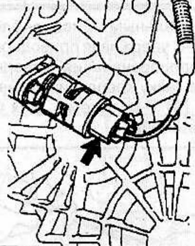
Disconnect the connector from the vehicle speed sensor.
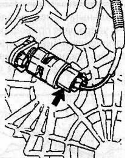
Unscrew and remove the vehicle speed sensor from the speedometer drive gear housing.
Mark the location of the speedometer drive gear housing. Remove the bolt, remove the retaining plate and take out the casing with the speedometer drive gear.
Using a special tool KM-468-C, hold the drive flange from turning, unscrew the nut and remove the flange from the transfer case.
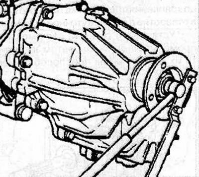
Remove the transfer case mode shift drive (see the relevant chapter).
Remove 11 bolts and remove the rear transfer case housing.
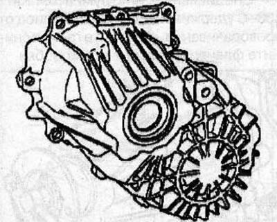
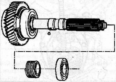
Remove the driven shaft from the rear case, then remove the snap ring from the groove in the rear case.
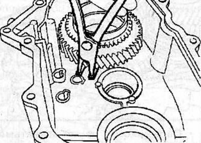
Remove the bearings and speedometer drive gear from the driven shaft.
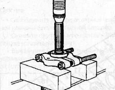
Place special clamps under the bearing and use a press to push the driven shaft out of the bearing.
Installation
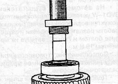
Using a special tool KM-778 (1) with an adapter KM-J-37486-A (2), press the front bearing onto the rear driven shaft.
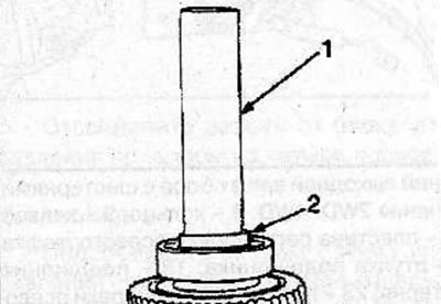
Use a new retaining ring to secure the bearing to the driven shaft.
Install the speedometer drive gear with the locking ball onto the driven shaft.
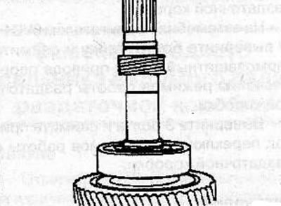
Using the special tool KM-778, install the rear bearing on the driven shaft.
Install the driven shaft assembly into the transfer case rear case and secure with the snap ring, making sure that the snap ring is correctly positioned in the groove of the rear case.
Apply a thin layer of sealant to the mating surfaces of the transfer case housing and rear case.
Make sure the tab (A) on the transfer case high/low shift block fits into the 2WD/4WD shift block.
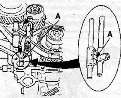
Set the high and low gear shift rod to position 4H.
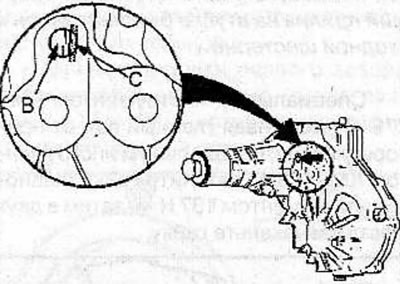
Install the rear transfer case housing. Align the shift rod (B) with the D-shaped hole (C) in the rear case.
Clean the threaded holes for the rear crankcase mounting bolts, then apply a layer of sealant to the bolt threads.
Install the rear crankcase mounting bolts and tighten to 37 Nm.
Install the transfer case mode switching drive (see the relevant chapter).
Using a special device KM-468-C, hold the drive flange from turning, screw on and tighten the flange mounting nut to a torque of 167 N·m, then pin the nut in two places.
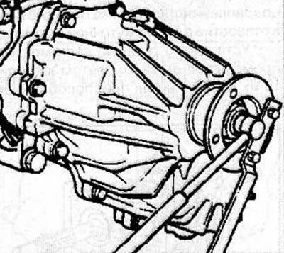
In accordance with the previously applied marks, install the casing with the driven gear of the vehicle speed sensor into the transfer case, install the retaining plate and secure with the bolt, tightening it to a torque of 15 N·m.
Screw the vehicle speed sensor onto the speedometer drive gear housing and tighten it to 27 N·m.
Connect the connector to the vehicle speed sensor.
Connect the cable to the negative terminal of the battery.
Visitor comments