


Contents: Removal ⬇ Installation ⬇
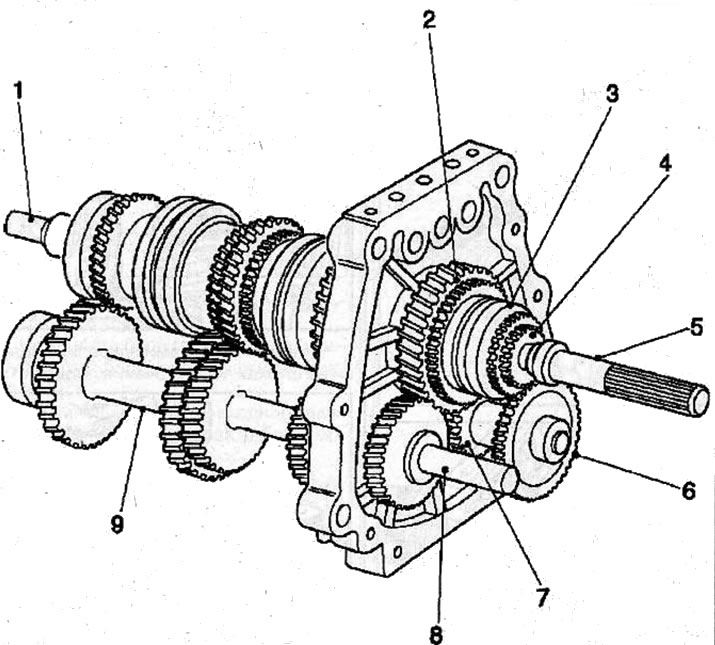
Shafts and gears: 1 - input shaft; 2 - reverse gear pinion; 3 - 5th gear/reverse gear synchronizer sleeve; 4 - 5th gear pinion; 5 - main shaft; 6 - 5th gear gear of the intermediate shaft; 7 - intermediate shaft reverse gear pinion; 8 - reverse gear pinion; 9 - intermediate shaft
Removal
Remove the gearbox housing from the intermediate plate (see the relevant chapter).
Remove the shift rods and forks from the intermediate plate (see the relevant chapter).
Using the KM-777, KM-777 and KM-210-V puller, remove the bearing seal and bearing from the main shaft.
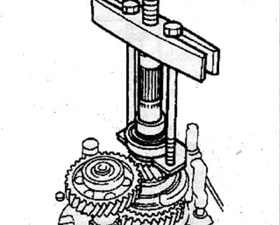
Remove the retainer, split thrust plate, thrust washer and locking ball from the main shaft.
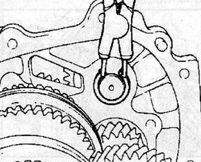
Remove the snap ring securing the reverse gear intermediate shaft to the transfer case, moving the shaft so that the locking pin on the side of the shaft gear can be removed.
Remove the snap ring securing the intermediate shaft rear bearing.
Using a two-jaw puller, remove the bearing and 5th gear from the intermediate shaft.
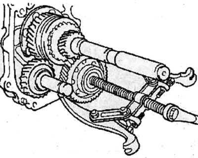
Remove the 5th gear intermediate shaft gear and the reverse gear intermediate shaft gear together.
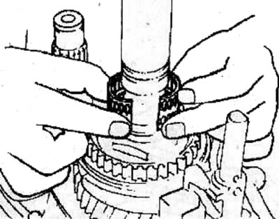
Remove the two halves of the 5th gear needle bearing and the synchronizer ring from the main shaft.
Install the input shaft bearing and the front intermediate shaft bearing in the special device KM-779.
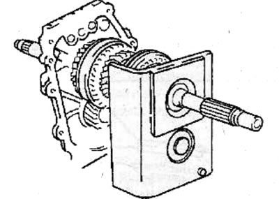
To prevent the main shaft from turning, engage 1st and 3rd gears simultaneously.
Using the special tool KM-776-A, unscrew the nut securing the 5th gear/reverse gear synchronizer sleeve to the main shaft.
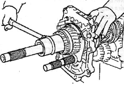
Remove the 5th/Reverse synchronizer sleeve, ring, needle bearing and reverse gear from the main shaft.
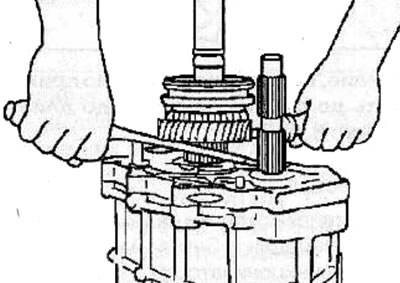
Using the special tool MKM-604-11, remove the main shaft bearing retaining plate from the intermediate plate.
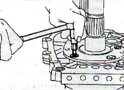
Remove the retaining ring securing the bearing to the intermediate plate.
Remove the main shaft retaining ring from the groove in the intermediate plate.
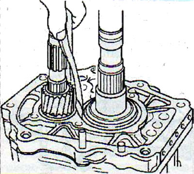
Remove the main shaft together with the intermediate shaft from the intermediate plate.
Remove the special device KM-779.
Remove the input shaft assembly from the main shaft.
If necessary, disassemble the input shaft, main shaft and intermediate shaft.
Installation
Install a new main shaft bearing retaining ring into the hole in the intermediate plate.
Install the main shaft together with the intermediate shaft, then secure them with a special device KM-779.
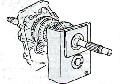
Install the shaft assemblies into the intermediate plate.
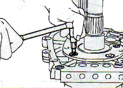
Apply locking compound to the threads of the main shaft bearing retaining plate mounting bolts, install the main shaft bearing retaining plate and tighten the bolts to 15 N·m using the MKM-604-11 special tool.
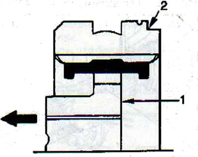
Install the reverse/5th gear synchronizer, aligning the flat side (1) of the hub with the groove (2) on the synchronizer sliding sleeve (the arrow points towards the reverse gear pinion).
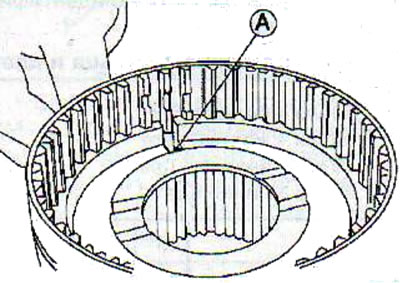
Warning! The location of the grooves on the hub must align with the locking crackers in the synchronizer hub (A).
Lubricate the bushing assembly with transmission oil and check for smooth movement.
Install the needle bearing, reverse gear pinion, synchronizer ring and reverse/5th gear synchronizer hub and secure with the nut to the main shaft.
Warning! To prevent the main shaft from turning, engage 1st and 3rd gears simultaneously.
Using the special tool KM-776-A, tighten the main shaft nut to a torque of 137 N·m.
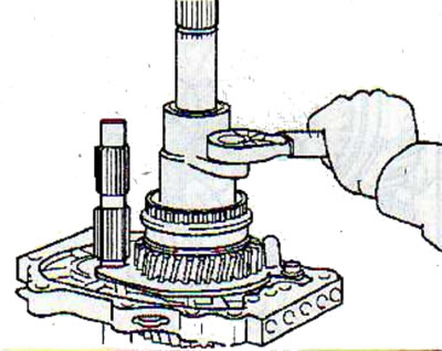
Using a hammer and punch, caulk the nut on the main shaft.
Install the reverse gear pinion onto the intermediate shaft with the protrusion on the pinion facing the bearing.
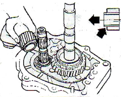
Install the thrust washer and lock pin onto the reverse idler gear shaft.
Install the two parts of the 5th gear needle bearing and the synchronizer ring onto the main shaft.
Using a soft hammer, install the 5th gear intermediate shaft gear and the reverse gear intermediate shaft gear together into the intermediate plate.
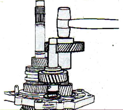
Make sure the idler gear shaft locking pin fits into the slot in the idler plate.
Install the rear bearing on the intermediate shaft opposite the 5th gear.
Measure the axial clearance between the bearing and the retaining ring.
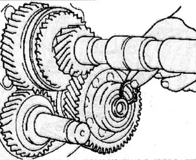
Select a snap ring of such thickness that it provides a minimum clearance between the bearing and the snap ring.
To adjust the axial clearance, retaining rings of different sizes are supplied, which are identified by a color mark.
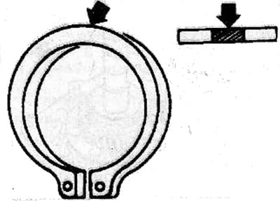
Retaining ring thickness and mark color
- 1.10 mm - white color
- 1.20 mm - yellow color
- 1.30 mm - blue color
- 1.40 mm - pink color
- 1.50 mm - green color
- 1.60 mm - brown color
Install the reverse gear intermediate shaft into the intermediate plate.
Measure the axial clearance between the retaining ring and the plate.
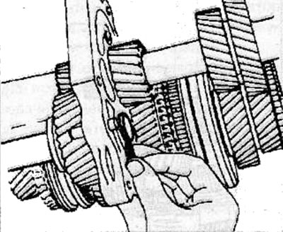
Select a retaining ring of such thickness that it provides a clearance between the retaining ring and the plate of 0-0.15 mm.
To adjust the axial clearance, retaining rings of different sizes are supplied, which are identified by a color mark.
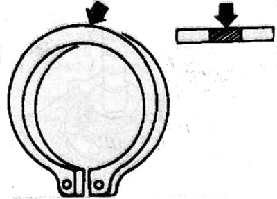
Retaining ring thickness and mark color
- 1.20 mm - white color
- 1.30 mm - yellow color
- 1.40 mm - blue color
Install the locking ball and thrust washer onto the main shaft.
Measure the axial clearance between the 5th gear pinion and the thrust washer.
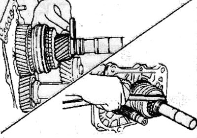
Select a thrust washer of such thickness that it provides a clearance of 0.10-0.25 mm.
To adjust the axial clearance, retaining rings of different sizes are supplied, which are identified by a color mark.
Retaining ring thickness and mark color
- 7.90 mm - white color
- 8.00 mm - yellow color
- 8.10 mm - green color
- 8.20 mm - blue color
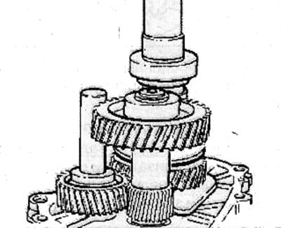
Install the split thrust plate and retainer onto the main shaft.
Using the special tool KM-778, install the rear bearing and bearing seal onto the main shaft.
Install the shift rods and forks onto the intermediate plate (see the relevant chapter).
Install the gearbox housing onto the intermediate plate (see the relevant chapter).
Visitor comments