


Contents: Removal ⬇ Installation ⬇
Removal
Remove the screws and handles from both gearbox and transfer case control levers.
Remove the lower instrument cluster trim and the rear and center console (see the relevant chapter).
Remove 3 screws and 2 nuts and remove the lever protective covers.
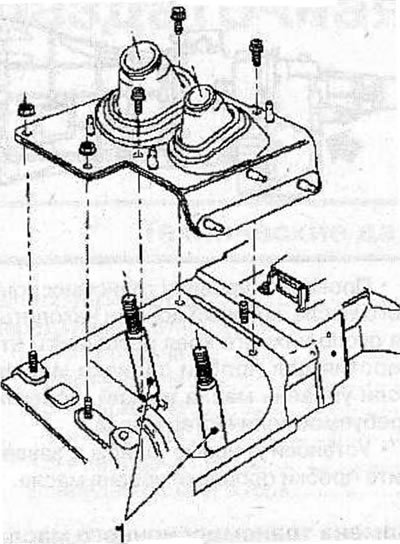
Remove the gearshift and transfer case control levers (1) (see the relevant chapter).
Raise the vehicle and support it on supports.
Remove the nuts and bolts and remove the engine compartment protection.
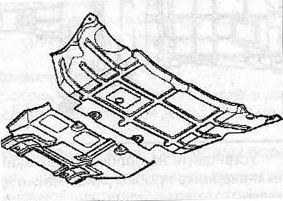
Remove the bolts and gearbox guard.
Remove the gearbox guard (1) and plate (3).
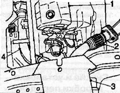
Remove the front exhaust pipes (2 and 4) (the picture shows the 6VD1 - W engine).
If major repairs are to be carried out on the gearbox and transfer case, remove the plugs and drain the transmission oil.
Mark the relative positions of the propeller shaft flanges and drive flanges on the front and rear axles.
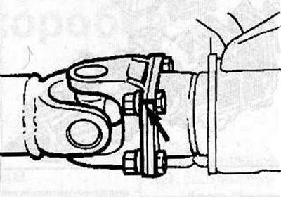
Loosen the nuts, remove the bolts and disconnect the rear propeller shaft flanges from the gearbox and rear axle.
Loosen the nuts, remove the bolts and disconnect the front propeller shaft flanges from the gearbox and front axle.
Disconnect the connectors from the 4WD switch (2), 4WD drive (1), speed sensor (6), and reverse light switch (4).
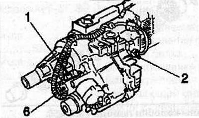
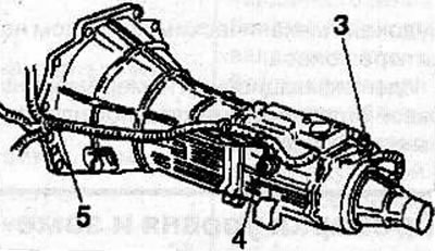
Release the clamps (3 and 5) and disconnect the wire harnesses from the transmission brackets.
Release the clamps and remove the fuel line heat shield from the transmission housing.
On a vehicle with a 6VD1-W engine, remove the heat shield from the wiring harness.
(Material was taken from a resource: www.OpelBook.ru)
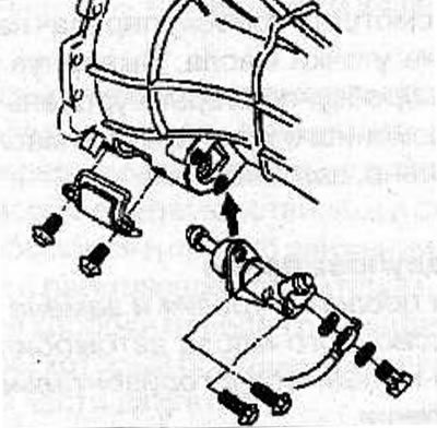
Remove the clutch slave cylinder (see the relevant chapter).
On a vehicle with a 6VD1-W engine, unscrew the 2 bolts and remove the cover that covers the clutch housing.
Use a jack to support the gearbox through a wooden block.
Loosen the nuts and disconnect the fuel lines from the rear beam.
Loosen the nuts securing the gearbox support to the rear beam.
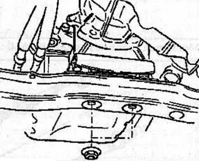
Remove the 6 bolts securing the rear beam to the vehicle chassis.
On a vehicle with a 6VD1-W engine, remove the starter (see the relevant chapter).
Remove the bolts and nuts and remove the cover to inspect the flywheel.
On a vehicle with a 6VD1-W engine, remove the traction type clutch. Insert the KM-J-39207 puller between the clutch release bearing and the thrust ring, then turn the puller to separate the clutch release bearing from the thrust ring, while the clutch release fork should move toward the gearbox.
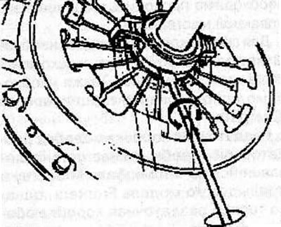
Warning: Make sure the puller is not inserted between the bearing and the clutch pressure plate diaphragm spring.
Remove the gearbox-to-engine mounting bolts, move the gearbox away from the engine, then slowly lower and remove the gearbox from under the vehicle.
When removing the gearbox, do not damage nearby components or the vehicle body.
Installation
Clean the mating surfaces of the gearbox housing and engine.
Clean the splines on the transmission input shaft and ensure that the clutch disc moves smoothly on the input shaft splines. If the disc is seizing on the input shaft or the clearance in the splines is increased, replace the clutch driven disc and/or the transmission input shaft.
Lubricate the clutch driven disc splines, bearing guide bushing and clutch release fork pivot points with general-purpose grease.
Use a jack to raise the gearbox to the required height.
Move the gearbox towards the engine, making sure that the longitudinal inclination of the gearbox matches the longitudinal inclination of the engine.
Align the transmission input shaft with the splined hole in the clutch driven disc.
On a vehicle with a 6VD1-W engine, tighten the transmission-to-engine mounting bolts as follows:
- bolts A: 76 Nm
- bolts B: 40 Nm
- bolts C: 8 Nm
- 2 bolts D: 8 Nm
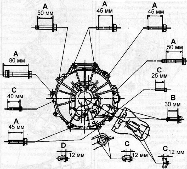
Location of gearbox mounting bolts to 6VD1-W engine
On a vehicle with an X 22 SE engine, tighten the transmission-to-engine mounting bolts as follows:
- m12 bolts: 76 Nm
- m10 bolts: 40 Nm
- bolts 6: 8 Nm
- bolts D: 60 Nm
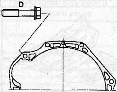
Location of D bolts for fastening the gearbox to the engine X 22 SE
On a vehicle with an X 22 DTH engine, tighten the transmission-to-engine mounting bolts as follows:
- bolts A: 76 Nm
- bolts B: 40 Nm
- 2 bolts C: 8 Nm
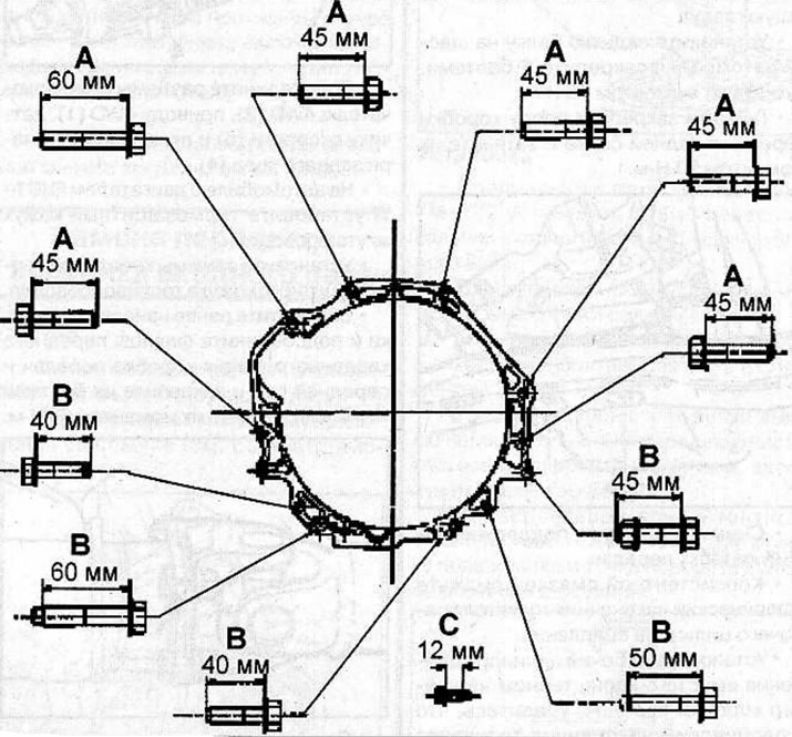
Location of gearbox to engine mounting bolts X 22 DTH
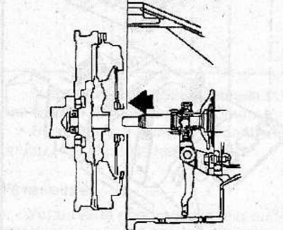
On a vehicle with a 6VD1-W engine, install traction type clutches. Place the clutch release bearing on the clutch pressure plate and apply a force of 6-8 kg to the end of the clutch release fork towards the gearbox, while the bearing should be secured on the pressure plate.
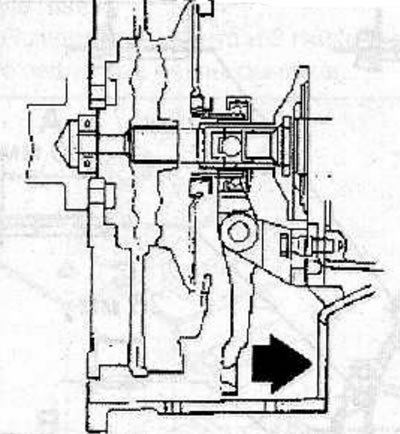
Warning! Check the reliability of the clutch release bearing connection to the pressure plate by pressing the fork with a force of 2.5 kg in the direction of the engine, while the fork should not move.
Install the flywheel inspection cover and secure with 2 bolts, tightening them to a torque of 11 Nm.
On a vehicle with a 6VD1-W engine, install a starter (see the relevant chapter).
Install the rear beam on the vehicle chassis, secure it with 6 bolts, tightening them to a torque of 76 Nm.
Use nuts to secure the gearbox support to the rear beam and tighten them to a torque of 50 Nm.
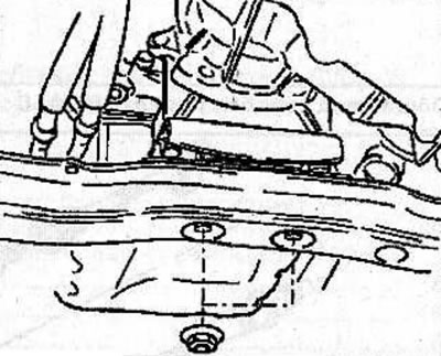
Remove the jack supporting the gearbox.
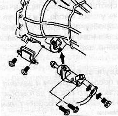
Lubricate the spherical tip of the clutch slave cylinder push rod with consistent grease.
Install the clutch slave cylinder together with the bracket onto the gearbox housing, ensure that the spherical tip of the pushrod is aligned with the clutch release fork, and tighten the bolts to a torque of 40 N·m.
On a vehicle with a 6VD1-W engine, install the clutch housing cover and secure with bolts, tightening them to a torque of 6 Nm.
Install the brackets on the gearbox housing and use clamps (3 and 5) to secure the wiring harness to the brackets.
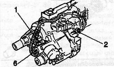
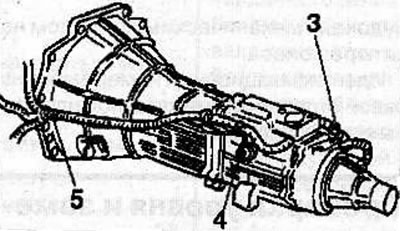
Connect the connectors to the 4WD switch (2), 4WD drive (1), speed sensor (6) and reverse light switch (4).
On vehicles with 6VD1-W engine, install the wiring harness heat shield.
Install the fuel line heat shield retaining clamps.
Align the previously applied marks and connect the front propeller shaft flanges to the gearbox and front axle and secure them with bolts and nuts, tightening them to a torque of 63 N·m.
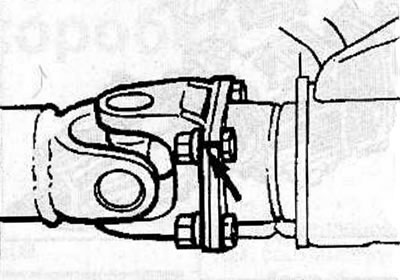
Align the previously applied marks and connect the rear propeller shaft flanges to the gearbox and rear axle and secure them with bolts and nuts, tightening them to a torque of 63 N·m.
Install the front exhaust pipes (2 and 4) (the picture shows the 6VD1-W engine).
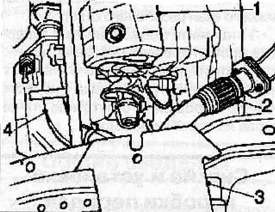
Install the gearbox guard (1) and plate (3).
Lower the car.
Install the gear shift and transfer case control levers (1) (see the relevant chapter).
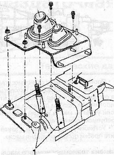
Install the protective covers of the levers and secure with screws and nuts,
Install the handles on the gearbox and transfer case control levers.
Check the transmission oil level in both the gearbox and transfer case (see the relevant chapter).
Install the lower instrument cluster trim and the rear and center console (see the relevant chapter).
Install the gearbox guard.
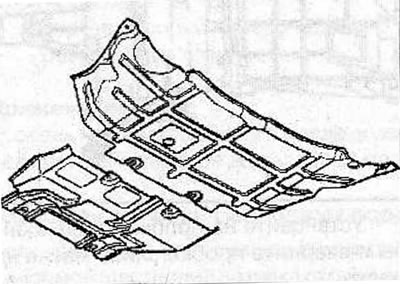
Install engine compartment protection.
Visitor comments