
Note: Before you start, see Chapter 2. A tachometer and an exhaust gas analyzer will be required to check the idle speed and mixture. If the cooling shroud has been removed, new O-rings will be required during installation.
Removing
1. Proceed as described in Chapter 17, points 1 and 2.
2. Note the position of the alignment marks of the bimetal casing to facilitate installation, if necessary, make the marks yourself, then unscrew the three fixing screws and remove the bimetal casing. Move the shroud to the side, being careful not to deform the coolant hoses or the throttle body heater wiring.
3. Unscrew the three screws securing the throttle body to the carburetor body, remove the throttle assembly, make sure that the damper drive rod is not bent.
4. If it is necessary to remove the bimetal cover for replacement, proceed as follows; otherwise go to step 8.
5. Mark the position of the automatic choke coolant hose to facilitate installation, then disconnect the hoses. Cap or secure hoses upside down to prevent loss of coolant.
6. Disconnect the electrical wiring from the electric damper heater, remove the bimetallic casing.
7. The cooling casing can be separated from the bimetal casing by unscrewing the central fastening bolt. Remove the O-rings from under the head of the bolt and from the frame of the cooling casing.
Installation
8. Position the choke assembly on the carburetor body; make sure that the lever on the damper assembly engages with the drive rod. Tighten the three fixing screws.
9. Check and, if necessary, adjust the air damper clearance and the position of the fast idle cam, as described in paragraphs 15-19 of this Chapter.
10. Connect the bimetallic spring to the damper lever, place the bimetallic casing on the damper casing, install the fastening screws. Align the marks on the bi-metal casing and damper casing as noted before removal, then tighten the fixing screws.
11. Where applicable, install the cooling shroud to the bimetal shroud, using a new O-ring, connect the coolant hoses and damper heater wiring.
12. Further installation is carried out in reverse order, paying attention to the following.
13. If the coolant hoses have been disconnected, check the coolant level as described in Section 3.
14. Check and, if necessary, adjust the increased idle speed, as described in paragraphs 25-34 of this Chapter.
Adjustment
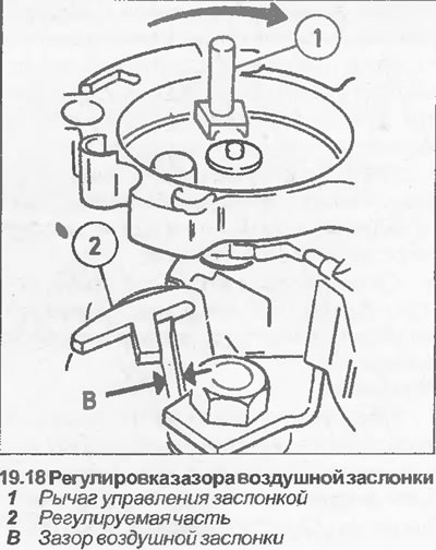
Air damper gap
15. Having removed the bimetallic casing, as described in paragraphs 2-4, proceed as follows.
16. Press the damper lever all the way clockwise, and fix it in this position with an elastic band.
17. Move the throttle lever to the fully open position, and measure the air damper gap between the underside of the damper and the primary chamber wall. Check that the gap matches the data in Specifications.
18. If necessary, adjust the air damper gap by bending "adjustable part (2) ". If the clearance is too small, increase the clearance "IN" with a screwdriver. If the clearance is too large, reduce the clearance "IN" with pliers (see illustration).
19. After adjustment, install the bimetal casing as described in points 10-14.
Fast idle cam position
20. Having removed the bimetal casing and correctly adjusted the gap of the air damper "IN", proceed as follows.
21. Open the throttle, then close the choke by lightly pressing your finger on the choke lever (see illustration). Close throttle.
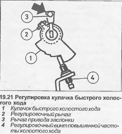
22. Check that the high idle adjusting screw touches the stop on the second step of the fast idle cam.
Fuel and Exhaust Systems - Carburetor Models
23. If adjustment is required, first check that the damper return spring is correctly positioned, then adjust by bending the lever.
24. Install the bimetal casing as described in paragraphs 10-14. Increased idle speed.
Note: An accurate tachometer and an exhaust gas analyzer will be required to make the adjustment (CO meter).
25. Check idle speed and mixture as described in Chapter 14. Before attempting to check or adjust the high idle speed, set the idle speed correctly.
26. Warm up the engine to normal operating temperature, connect a tachometer according to the manufacturer's instructions, and then proceed as follows.
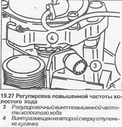
27. Place the fast idle adjusting screw on the second step of the fast idle cam (see illustration).
28. Start the engine without touching the gas pedal, and check that the increased idle speed is within the indicated limits. If adjustment is required, turn off the engine and proceed as follows.
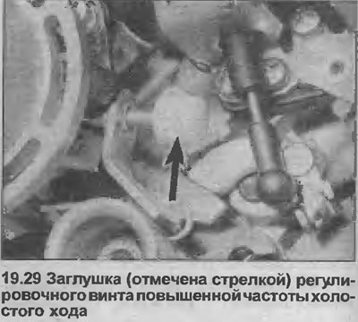
29. Remove the plug from the high idle adjusting screw (see illustration).
30. Check that the adjusting screw rests on the second fast idle cam step from the top, then start the engine without touching the gas pedal.
31. Turn the adjusting screw with a screwdriver until you get the high idle speed specified in the Specifications.
32. If the cooling fan turns on during adjustment, stop the adjustment and continue only after the fan turns off.
33. At the end of the adjustment, turn off the engine and disconnect the tachometer.
34. Install a new plug on the high idle adjusting screw.
Visitor comments