
Main Diaphragm Unit
Note: See Chapter 2 before starting work. A new star bracket must be used when installing the diaphragm assembly. Check the vacuum chambers as described in Chapter 16 paragraph 1.
Removing
1. Proceed as described in Chapter 17, points 1 and 2.
2. Disconnect the vacuum tubes from the diaphragm assembly.
3. Use a punch to knock out the roll pin securing the diaphragm assembly to the carburetor top cap.
4. Note the position of the alignment marks of the bimetal casing to facilitate installation, if necessary, make the marks yourself, then unscrew the three fixing screws and remove the bimetal casing. Move the casing to the side, then be careful not to deform the coolant hoses or the wiring of the damper heater.
5. Remove the three screws securing the throttle assembly to the carburetor body. Allow the damper assembly to drop down, but do not disconnect the damper rod.
6. Remove the star bracket that secures the diaphragm assembly to the carburetor top cap and remove the diaphragm assembly.
Installation
7. Install in reverse order, but use a new star bracket that secures the diaphragm assembly to the carburetor top cap. Before installing the air block on top of the carburetor, check and, if necessary, adjust the pull-down flap as follows.
Vacuum pull-down
Adjustment
8. After removing the air filter or air block from the top of the carburetor as described in Chapter 17 point 2, proceed as follows.
9. Note the position of the alignment marks of the bimetal casing to facilitate installation, if necessary make marks yourself, then unscrew the three fixing screws, and remove the bimetal casing. Move the casing to the side, then make sure that the coolant hoses or the electrical wiring of the damper heater are not deformed.
10. Place the high idle adjusting screw on the highest step of the fast idle cam and check that the choke is closed.
11. Move the pull-down lever towards the diaphragm assembly, pushing the adjusting screw until resistance is felt. Lock the lever in this position.
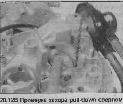
12. With a drill of the appropriate diameter, measure the gap between the underside of the damper and the wall of the primary chamber (see illustrations). Check that the clearance is as given for "small" pull-down damper clearance in Specifications.
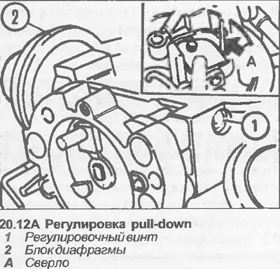
13. If adjustment is necessary, turn the adjusting screw in the appropriate direction until the clearance is correct.
14. Now push the pull-down lever against the diaphragm assembly as far as it will go, and lock the lever in that position.
15. As before, measure the gap between the underside of the damper and the wall of the primary chamber. Check that the clearance is as given for "big" pull-down damper clearance in Specifications.
16. If adjustment is necessary, turn the adjusting screw in the appropriate direction until the clearance is correct.
17. Connect the bimetal spring to the damper lever, place the bimetal casing on the damper casing, and loosely install the fixing screws. Align the marks on the bi-metal casing and damper casing as noted before removal, then tighten the fixing screws.
18. Install the air block on top of the carburetor.
Winding secondary pull-down
Removing
19. This unit works in conjunction with the main diaphragm unit.
20. To remove the winding, first proceed as described in Chapter 17 points 1 and 2.
21. Disconnect the diaphragm assembly vacuum tube.
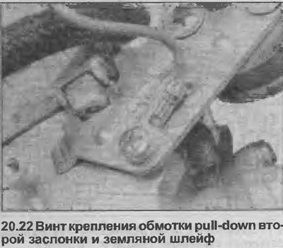
22. Disconnect the electrical wiring, then unscrew the mounting screw, and remove the winding block and mounting bracket from the carburetor. Note that the mounting screw also secures the ground loop of the wiring connector (see illustration).
Installation
23. Install in reverse order, but be sure to secure the ground cable under the pull-down winding bracket screw.
Visitor comments