
OpelBook.ru
Cars AvtoVAZ Cars Mitsubishi Cars BMW Cars Mercedes Cars Nissan Cars Toyota Cars Chevrolet
English Русский
Български
Беларускі
Український
Српски
Hrvatski
Română
Polski
Slovenský
Magyar
 |  Sitemap  |  Contacts  |    


Main Astra Corsa Insignia Kadett Omega Vectra Zafira Others Articles
Astra F (1991-1998, petrol) Astra G (1998-2004, petrol) Astra G (1998-2004) Astra H (2004-2009) Astra J (2009-2015, petrol)
  • Main
  • Astra
  • Astra F
  • Power unit
  • Fuel supply (carburetor)
  • Vacuum regulator for opening the automatic air damper — removal, installation and adjustment

Vacuum regulator for opening the automatic air damper — removal, installation and adjustment (Opel Astra F)

            0

Contents: Main diaphragm assembly ⬇ Secondary air damper opening solenoid ⬇ Adjusting the vacuum device for…⬇

Main diaphragm assembly
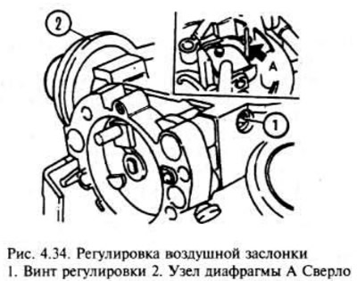


Main diaphragm assembly


Disconnect the negative battery terminal, air cleaner hoses and remove the air box.

Disconnect the diaphragm assembly vacuum tubes.

Using a suitable punch with a thin cylindrical end, knock out the round pin (axis of rotation) fastening the diaphragm assembly to the top cover of the carburetor.

Mark the position of the housing marks, bimetallic. spring, to make it easier to install later, then unscrew the three screws and lift the spring housing. Move it to the side, trying not to stretch the hoses or electrical wiring of the air damper heater.

Remove the three screws securing the choke assembly to the carburetor body. Let the choke assembly hang down, but do not disconnect the choke linkage.

Remove the star clamp securing the diaphragm assembly to the carburetor cover and pull out the diaphragm assembly.

Installation is the reverse of removal, but a new star-shaped clamp must be installed to secure the diaphragm to the top cover of the carburetor. Before installing the airbox on the top of the carburetor, check and, if necessary, adjust the choke opening as described in this section.


Secondary air damper opening solenoid
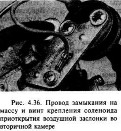


Secondary air damper opening solenoid


The solenoid works in conjunction with the carburetor primary chamber diaphragm.

Disconnect the negative battery terminal, air cleaner hoses and remove the air box.

Disconnect the vacuum tube of the diaphragm device.

Disconnect the wiring, then remove the screw and separate the solenoid and its bracket from the carburetor. Remember that the screw also secures the ground wire.

Installation is carried out in the reverse order of removal. Check that the ground wire is in place under the solenoid bracket screw.

Adjusting the vacuum device for opening the air damper


After removing the air box from the top of the carburetor, the procedure is as follows.

Note the position of the marks on the bimetallic spring housing, then remove the three screws and lift the spring housing. Move it to the side, being careful not to stretch the cooling hoses and the air damper heater wiring.

Set the fast idle adjustment screw to the highest step of the cam and check that the choke is closed.
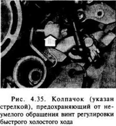
Set the fast idle adjustment screw to the highest step of the cam and check that the choke is…


Move the lever towards the diaphragm device, pressing the adjusting screw until it stops. Keep the lever in this position.


Using a drill bit of the appropriate diameter or similar tool, measure the clearance between the underside of the throttle body and the wall of the primary chamber diffuser. It should match the specification under "small clearance" ("Carburetor Parameters. Clearance of Half-Opened Choke").
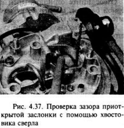
Using a drill bit of the appropriate diameter or similar tool, measure the clearance between the…


If adjustment is necessary, turn the adjusting screw in the appropriate direction with an end wrench.

Now push the opening lever towards the diaphragm device until it stops and hold it in this position.

As above, measure the gap between the underside of the air damper and the wall of the primary chamber diffuser. It should match the specification under "Large Clearance".

If adjustment is necessary, turn the adjusting screw in the appropriate direction.

Attach the bimetallic spring to the air damper lever, install its housing on the damper housing and "tighten" the mounting screws. Align the marks on the spring housing and the damper housing, then tighten the screws.

Install the air box on the top of the carburetor after completing the adjustment.

[Original posted on the website: www.opelbook.ru]


This article is available at russian, bulgarian, belarusian, ukrainian, serbian, croatian, romanian, polish, slovak, hungarian
Checking the article: Trifonova Emilia

Share information:

Previous articles
Opel Astra F: Fuel supply (carburetor)
Next articles

Automatic air damper — removal, installation, adjustment
Carburetor Accelerator Pump Diaphragm — Replacement
Carburetor Economizer Diaphragm — Replacement
Secondary chamber vacuum diaphragm throttle control
Carburetor float and needle valve — removal, inspection and installation
Carburetor — diagnostics of faults, repair and adjustment
Intake manifold — removal and installation
Exhaust manifold — removal and installation
Exhaust system — general information
Exhaust system — replacement of parts


See similar ones from other Opel car manuals:
▶ Automatic Air Damper Pull-Down Vacuum Blocks — Removal,… Opel Vectra A (1988-1995, petrol)
▶ Carburetor Throttle Damper (Automatic Transmission Models)… Opel Omega A (1986-1993)
▶ Automatic dynamic headlight range adjustment Opel Insignia A (2008-2017)
▶ Checking the opening time of the starting air damper Opel Kadett D (1979-1984)
▶ Automatic transmission mode selector cable — replacement… Opel Zafira A (1999-2005, petrol)
Link to this page in different formats

Visitor comments


No comments yet


How much will 41 + 38 =


Astra J (2009-2015, petrol) 
  • General information
  • Vehicle device
  • User manual
  • Faults en route
  • Maintenance
  • Power unit
  • Engine repair
  • Cooling and lubrication system
  • Engine power system
  • Exhaust system
  • Transmission
  • Clutch
  • Car gearbox
  • Drive shafts
  • Chassis
  • Front suspension
  • Rear suspension
  • Steering
  • Brake system
  • Wheels and tires
  • Body
  • Exterior
  • Interior
  • Doors and windows
  • Body Care
  • Heating and air conditioning
  • Security systems
  • Electrical equipment
  • Equipment and devices
  • Lighting and signaling
  • Power devices
  • Electrical circuits
Astra H (2004-2009) 
  • General information
  • Introduction to the guide
  • Troubleshooting
  • User manual
  • Maintenance
  • Power unit
  • Engine repair
  • Cooling and heating
  • Power and exhaust system
  • Ignition system
  • Launch and charge system
  • Transmission
  • Mechanical gearbox
  • Automatic gearbox
  • Drive shafts
  • Chassis
  • Brake system
  • Car suspension
  • Steering
  • Body
  • Interior
  • Exterior
  • Electrical equipment
  • Equipment and devices
  • Electrical circuits
Astra G (1998-2004) 
  • General information
  • Introduction to manual
  • User manual
  • Maintenance
  • Power unit
  • SOHC gasoline engines
  • DOHC gasoline engines
  • Diesel engines 1.7 and 2.0
  • Engine repair
  • Cooling system
  • Supply system
  • Injection system (gasoline)
  • Injection system (diesel)
  • Exhaust system
  • Charge and launch system
  • Ignition system (gasoline)
  • Preheat system (diesel)
  • Transmission
  • Manual gearbox
  • Automatic gearbox
  • Clutch
  • Drive shafts
  • Chassis
  • Brake system
  • Wheel suspension
  • Steering
  • Body
  • Exterior
  • Interior
  • Doors and windows
  • Ventilation and heating
  • Electrical equipment
  • Equipment and devices
  • Electrical circuits
Astra G (1998-2004, petrol) 
  • General information
  • User manual
  • Car care
  • Maintenance
  • Power unit
  • Single shaft engines
  • Twin shaft engines
  • Engine repair
  • Cooling and heating
  • Fuel and exhaust systems
  • Starting and charging system
  • Ignition system
  • Transmission
  • Clutch
  • Mechanical gearbox
  • Automatic gearbox
  • Drive shafts
  • Chassis
  • Brake system
  • Car suspension
  • Steering
  • Body
  • Interior
  • Exterior
  • Electrical equipment
  • Equipment and devices
  • Wiring diagrams Opel Astra
  • Wiring diagrams Opel Zafira
Astra F (1991-1998, petrol) 
  • General information
  • Maintenance
  • Power unit
  • Engine in car
  • Engine removed
  • Cooling system
  • Heating and ventilation
  • Fuel supply (carburetor)
  • Fuel supply (injector)
  • Emission control
  • Ignition system
  • Transmission
  • Clutch
  • Mechanical gearbox
  • Automatic gearbox
  • Drive shafts
  • Chassis
  • Brake system
  • Car suspension
  • Steering
  • Body
  • Exterior
  • Interior
  • Electrical equipment
  • Equipment and devices
  • Electrical circuits
OpelBook.ru © 2017–2026 · Mobile version · · Sitemap: EN BG BY UA RS HR RO PL SK HU · Feedback · Site search
Astra F, petrol · Astra G, petrol · Astra G · Astra H · Astra J, petrol · Corsa B · Corsa C, petrol · Corsa C · Insignia A · Kadett D · Kadett E · Omega A · Omega B · Omega B2 · Vectra A, petrol · Vectra A · Vectra B, petrol · Vectra B · Vectra C · Zafira A, petrol · Frontera A, petrol · Frontera B · Ascona C · Vivaro A ·
We want your visit to be comfortable 🤝! We use cookies 🍪 to make that happen.