
Fixed steering column
Bulkhead
1. If the steering column has not yet been removed from the vehicle, proceed as described in paragraphs 1-11 Chapter 33.
2. Remove, using a screwdriver as a lever, the fuses from the ignition switch housing, see illustration), then turn the cover counterclockwise and remove it from the steering column.
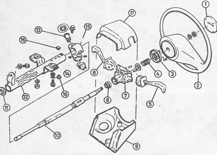
34.2 Fixed steering column components
1 Horn key
2 steering wheel
3 Assembly of the cam
4 Spring
5 Combined headlight/turn signal switch
6 Washer/wiper switch
7 Switch cover
8 Bearing
9 Steering column lower cover
10 Steering shaft
11 Centering plastic washers
12 Steering column tube
13 Lock cylinder
14 Ignition switch
15 Lock cover
16 Switch housing fuses
17 Upper casing of the steering column
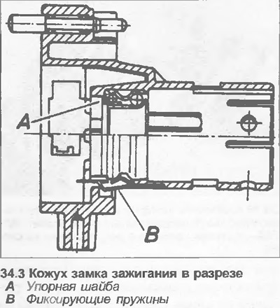
3. To remove the bearing from the ignition lock housing, use a screwdriver to pry out the two fasteners of the bearing and force or knock it out by installing a tubular drift on the outer race of the bearing. When installing a new bearing, make sure the thrust washer and retaining springs are installed correctly) (see illustration).
4. The ignition lock is attached to the steering column lock housing with two countersunk head screws. Loosen the screws and remove the lock. It is recommended not to remove the switch and the lock cylinder at the same time so that their relative position is not lost.
5. If the steering column is in the vehicle, twist and remove the upper steering shaft flex coupling pinch bolt in the driver's footwell.
6. Remove the steering gear shaft from the steering column tube.
7. Install the temporary plastic centering washer provided with the new steering column or steering shaft into the base of the steering column tube.
8. Insert the shaft into the steering column tube. If the steering column is in the vehicle, connect the lower end of the shaft to the flexible coupling and install the upper pinch bolt, but do not tighten it at this stage.
9. Install the ignition switch and tighten the countersunk screws.
10. Install the ignition switch cover using new fuses.
11. If the steering column is in the vehicle, pull the steering shaft up to the bearing stop, then tighten the upper flex coupling pinch bolt. Make sure the wheels are still in the straight ahead position and the top flex coupling pinch bolt is horizontal.
12. Next, install in the reverse order of removal. Install the steering wheel as described in Chapter 30.
13. Finally, test drive the route with several turns and check that the steering mechanism is working properly.
Tilt steering column
Note: When reassembling, use new shear bolts to secure the lock case.
Bulkhead
14. If the steering column is in the car, proceed as described in points 1-11 Chapter 33.
15. Remove the tilt adjuster spring using a screwdriver as a lever. Be careful as the spring may fly out.
16. The ignition lock is attached to the lock casing with two countersunk screws. Access to the countersunk screw is virtually impossible without removing the steering column. Remove it as described in Chapter 33.
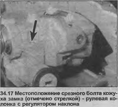
17. The lock housing is attached to the bearing housing with two shear bolts, which must be punched, drilled and removed using a special bolt remover (see illustration).
18. Steering column upper bearing ring can be replaced after removal of retaining ring, compression rings and spring. Note that it may be necessary to compress the spring to remove the circlip. Be careful as the spring may fly out after removing the circlip.
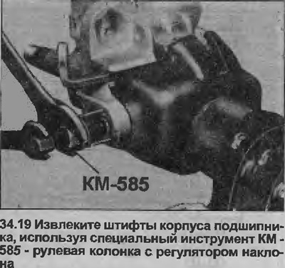
19. To remove the bearing housing from the steering column, remove the pins using the nut and bolt. For this purpose, there is a special tool Opel KM-585 (see illustration).
20. The steering column lower bearing race can be removed from the shaft using a hammer and drift or flat chisel. Install a new ring on the shaft.
21. The main steering column bearing rings can only be replaced together with the casing.
22. If necessary, remove the shaft universal joint and the tilt adjustment locks for replacement
23. Install the components in the reverse order of removal, paying attention to the following (see illustration).
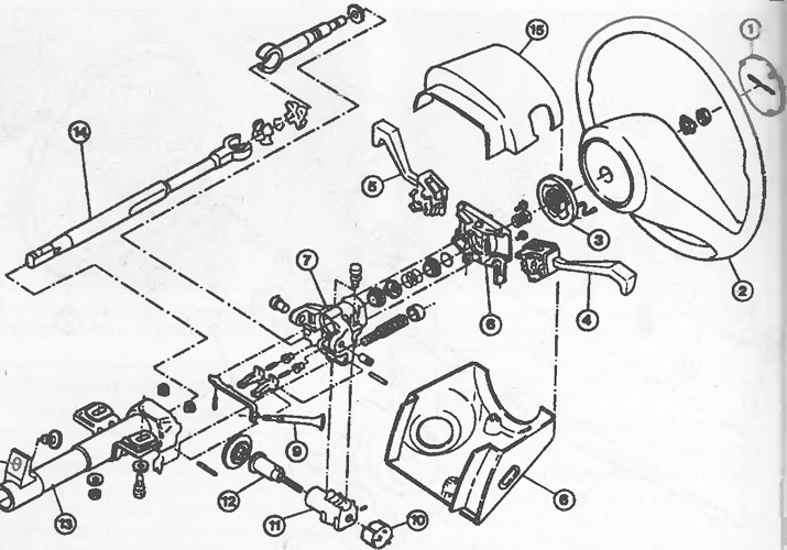
34.23 Tilt steering column components
1 Horn key
2 steering wheel
3 Assembly of the cam
4 Combined headlight/turn signal switch
5 Washer/wiper switch
6 Switch cover
7 Bearing housing
8 Steering column lower cover
9 Tilt lever
10 Ignition switch
11 Lock cover
12 Lock cylinder
13 Steering column tube
14 Steering shaft
15 Upper casing of the steering column
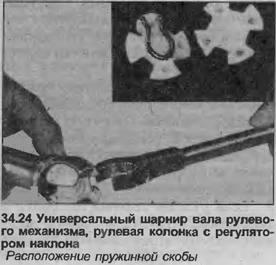
24. When installing the universal joint of the steering shaft, please note that the spring clips must fit into the recesses of the halves of the joint (see illustration).
25. If the lock casing and the bearing housing were separated from each other, clean the holes for the fastening bolt using a special threaded plug. Apply blocking compound to the new shear bolts and tighten them until the heads break off.
26. After installing the bearing housing pins, secure each pin at three equally spaced locations.
27. When replacing bearings, make sure that the clearances between the bearing housing and the buffers that restrict upward movement are the same. Measure the gaps with a feeler gauge. On sale there are sets of buffers of various thicknesses.
Visitor comments