


Contents: Removal ⬇ Installation ⬇
Note: You will need a bolt puller. When installing the steering column, use a new shear bolt and (where it is applied) new self-locking nut. Please note that on models equipped with air springs, two additional struts are installed between the steering column and the central floor tunnel.
Removal
1. Disconnect the negative cable from the battery.
2. Set the front wheels in the straight ahead position.
3. Working in the driver's footwell, remove the lower trim panel.
4. On models with tilt steering column, move the steering column to the fully raised position, then loosen the adjuster lever.
5. For better access, remove the steering wheel as described in Chapter 30.
6. Using a screwdriver as a lever, remove the screw covers from the front side of the steering column covers, then remove the cover mounting screws.
7. Remove the three screws from the back of the lower steering column cover, then remove both covers.
8. Disconnect the wiring connectors from the ignition switch and the ignition switch and windshield wiper switches. Disconnect the horn switch wires from the lock housing.
9. On models with a fixed steering column, press the ignition switch and windshield wiper switch mounting brackets and remove the switches. On models with a tilt steering column, remove the two screws securing the ignition switch/windshield wiper switch assembly to the steering column and remove the assembly.
10. Insert the key into the ignition switch and turn it to position "II".
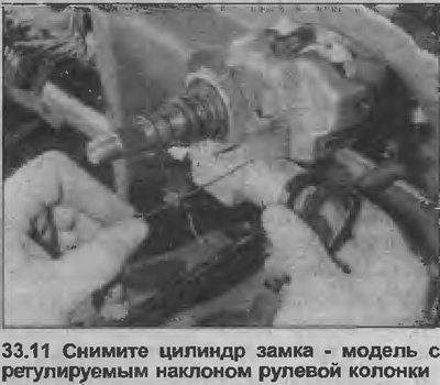
11. Insert a thin rod into the hole in the lock casing, press it to release the lock spring, and remove the lock cylinder using the key (see illustration).
12. Working at the lower end of the steering shaft, loosen and remove the upper tie bolt securing the steering shaft to the flexible coupling.
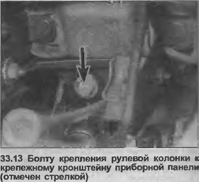
13. Loosen and remove the bolt securing the steering column to the instrument panel mounting bracket (see illustration).
14. Remove the two bolts from the upper steering column bracket. The right side bolt is a shear type and must be punched, drilled out and removed with a special bolt puller. The left side uses a regular bolt or self-locking nut.
15. Remove the steering column assembly into the vehicle interior, then remove it from the vehicle. Handle the steering column carefully, avoiding any impact or shock that may damage the deformable portion of the steering column housing.
16. If necessary, rebuild the steering column as described in Chapter 34.
Installation
17. Make sure the wheels are still in the straight ahead position and the upper flex coupling pinch bolt is horizontal on the steering gear shaft.
18. The new steering column assembly purchased for replacement will have a large plastic washer installed at the base of the steering column tube. This washer is used to center the shaft in the tube and should be removed after installation is complete.
(Article published on the website www.OPELBOOK.ru)
19. Reinstall the steering column and fit the flexible coupling. Fit the pinch bolt, but do not tighten it completely at this stage.
20. Reinstall the top mount bolts using a new shear bolt and (where it is applied) new self-locking nut.
21. Install the bolt securing the steering column to the instrument panel bracket and tighten it to the torque specified in the Specifications.
22. Tighten the top mount bolts. Tighten a shear bolt until its head breaks off, a regular bolt or a self-locking nut (depending on the model) must be tightened with a tightening force specified Specifications.
23. Pull the steering gear shaft up to the bearing stop, then tighten the upper pinch bolt of the flexible coupling
24. Using a screwdriver as a lever, remove the plastic centering washer from the base of the steering column tube and the steering gear shaft.
25. Further installation is carried out in the reverse order of removal. Install the steering wheel as described in Chapter 30.
26. Finally, take the vehicle for a test drive on a route with several turns and make sure the steering mechanism works properly.
Visitor comments