


Note: Replace both sets of brake pads at the same time - never replace the pads on just one wheel, this may result in uneven braking.
Place chocks under the front wheels, then raise the rear of the car and support it securely with stands under the axle.
Working from one side of the vehicle, remove the brake drum as described in the next section.
Note the location and direction of all components before disassembling.
Remove dust and dirt from the drum and brake shoes, being careful not to inhale dusty air.
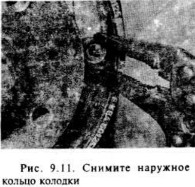
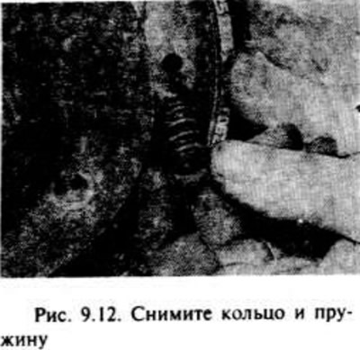
Remove the brake shoe support pins, springs and support rings by pressing on the rings and turning them 90° with pliers. Note that the support pins are removed through the brake shoe support disc (fig. 9 11. 9.12).
Disconnect the handbrake cable from the lever.
The upper and lower tension springs can now be disconnected (remove hooks) and remove the pads separately, or the pad assembly, adjusting mechanism rod and springs can be removed together (see chapter 10). Try not to damage the rubber boots of the wheel brake cylinders. Before removing the tension springs, note the location of the springs and the adjusting mechanism
If the shoes need to be removed temporarily, secure the wheel brake cylinder with a strong rubber band or spring clamp to prevent the pistons from being pushed out of the holes. In any case, do not press the brake pedal while removing the drum.
Remove dust and dirt from the brake pad backing plate, being careful not to inhale dusty air.
Apply a small amount of brake grease to the friction surfaces of the support disc.
If the brake linings are contaminated with brake fluid or grease, locate the source of contamination before installing new linings (the wheel brake cylinder or hub bearing seal is leaking).
Although friction brake linings are purchased separately (without brake pads), preference is given to replacing the brake pads together with the friction linings.
Disassemble the brake shoes, adjuster rod and springs. Note the location of the parts.
When disassembling both brake mechanisms at the same time, try not to mix the parts. The parts are marked to indicate left-hand and right-hand parts: the threaded rod is marked L and R (L is left and R is right), and on other parts the left side is marked in black, and the right-hand part is marked in silver.
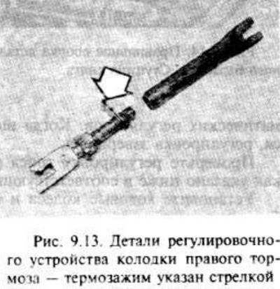
Remove and wipe away any dirt from the adjuster rod. Apply a small amount of silicone grease to the adjuster rod threads. If new Z friction brake linings and shoes need to be installed, the heat-shrink clip on the adjuster rod must also be replaced (Fig. 9.13).
Original article on the web portal www.opelbook.ru
Check the tension springs. If they are defective or heavily worn, it is recommended to replace them. Weak springs can cause the brakes to stick
The assembly of the unit can be carried out in the form of an angle. Install the pads on the support disk. Try not to damage the rubber covers of the wheel cylinder or displace the pistons.
After installing the pads in place, insert the support pins and secure them with the springs and rings.
Install the handbrake cable, then install the bushing if necessary.
If assembling the legal unit seems too difficult, then you can install the pads and secure them with support pins, then insert the adjusting rod and install the springs and adjusting mechanism.
Turn the fine adjustment knob out to reduce the rod protrusion until the brake drum seats on the shoes.
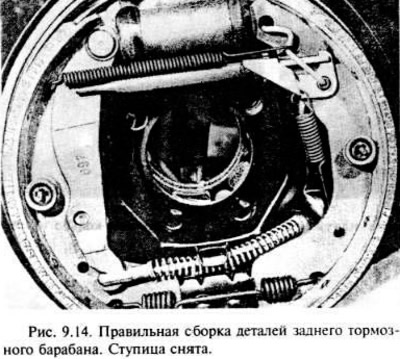
Make sure that the handbrake lever is installed correctly, that the pin is against the arch of the shoe, then install and secure the brake drum (Fig. 9.14).
Repeat the operations with the brake mechanism on the other side of the car.
Adjust the brakes by checking the foot brake about fifteen times. A clicking sound will be heard in the drums as the automatic regulators operate. When the clicking stops, the adjustment is complete.
Check the handbrake cable adjustment as described in the relevant section below.
Install the road wheels and lower the vehicle to the ground.
New brake pads need to be gradually worked in, so try to avoid hard braking during the first 100 miles of driving.
Visitor comments