


Attention: It is necessary to replace all brake pads of one axle of the vehicle at the same time, even if only one of them has reached the wear limit! Use only pads approved for use by the manufacturer!
Removal
Caution: After removing the brake pads, do not press the brake pedal, otherwise the piston may be pushed out of the housing. In this case, you will have to go to a service station to install the piston back.
1. Set the parking brake, jack up the front of the car and place it on supports. Remove the front wheels.
2. Disconnect the brake pad wear sensor wiring connector, release the wiring harness from the intermediate holders and move it to the side (see accompanying illustration).
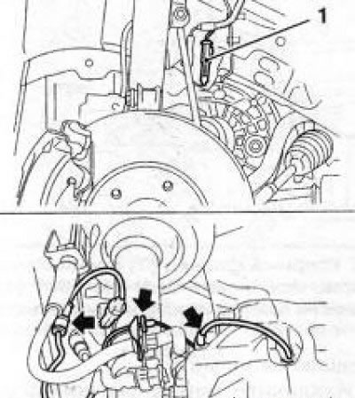
5.2 Disconnecting the brake pad wear sensor wiring (left caliper)- the arrows indicate the harness holders: 1. Electrical wiring connector
3. Using a screwdriver, disconnect the spring clips (see accompanying illustration) brake pads from the caliper and remove them.
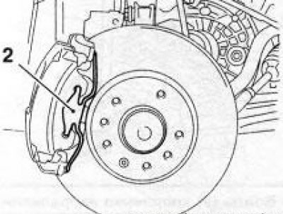
5.3 Spring clamp (2) of the front wheel brake mechanism
4. Remove the dust caps from the caliper guide pin holes (see accompanying illustration). Be careful not to damage the ABS wheel sensor wiring.
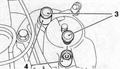
5.4 Dust caps (3) of guide pins (4) of caliper
Note: The brake hose does not need to be disconnected from the caliper as shown in the illustration.
5. Unscrew the guide pin mounting bolts and remove the caliper with the inner brake shoe (see accompanying illustration). Remove the inner pad with the wear indicator from the caliper and tie the caliper to the strut with a piece of wire, do not leave it hanging on the hose.
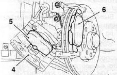
5.5 Removing the inner (5) and outer (6) brake pads of the front wheels: 4. Support
6. Remove the outer shoe (see illustration 5.5) from the guide.
Attention: If you plan to reinstall the same brake pads, you must mark their installation locations when removing them. It is not allowed to switch the brake pads from the outer side to the inner side and from the right wheel to the left!
Examination
7. Sweep away any dust that has accumulated on the surfaces of the brake components (see Precautions in Section 1). Wipe the caliper and piston end surface with a clean rag. Remove rust from the edge of the brake disc.
8. Check the condition and thickness of the brake pads (see Chapter 1, Section 14) Oily pads must be replaced without fail, first eliminate the cause of the leak. Check the surface of the brake disc with your fingers by touch. A brake disc with unevenness can be turned, if it is thick enough - contact a specialist.
Note: Both brake discs on the same axle must be machined to the same thickness.
If the disc thickness has reached its wear limit (see Specifications), replace both discs of one axle.
9. If the condition of the brake pads and disc is found to be satisfactory, thoroughly clean them and the contact surfaces of the brake discs from dirt with a soft wire brush, paying special attention to the back and sides. Clean the grooves in the friction linings, completely removing foreign inclusions from them. Clean the seating places of the pads in the caliper and anchor bracket. After this, wipe all mating surfaces with a rag moistened with alcohol.
Caution: Use only alcohol to clean the brakes, and do not use tools with sharp edges to avoid damaging the sealing cuffs!
10. The guide pins should move easily in the caliper bushings; clean the pins if necessary. Check the condition of the piston sealing cuff, inspect the piston for signs of developing brake fluid leaks, traces of corrosion and mechanical damage. Replace defective components. Disassembling the caliper for restoration repairs and replacing the piston cuff should only be done at a service station.
Installation
11. When installing new pads, the piston must be pressed into the caliper cylinder to free it up for installing thicker new pads. The piston is pressed out using a special device (for example,Hazet 4970/6), although a suitable sized clamp or wooden lever will work just as effectively, if necessary, place an old brake shoe as a support surface in front of the piston. Be careful not to damage the piston surface and protective cap. When the piston returns, brake fluid is squeezed out of the brake cylinder into the reservoir, so the reservoir cap must be removed. To prevent brake fluid from leaking, first check its level - if necessary, pump out excess.
Caution: Pressing the piston down carries the risk of damaging the sealing lip and the piston surface - use caution!
12. Before installing new brake pads, clean the mating surfaces of the brake mechanism and guides. Lubricate the guide surfaces of the pads (see accompanying illustration) a thin layer of heat-resistant grease (for example, with Liqui Moly paste).
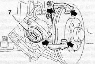
5.12 Lubrication points (indicated by arrows) brake shoe guide: 7. Brake piston
13. Insert the outer brake pad into the guide and the inner brake pad with the wear indicator into the caliper (see illustration 5.5)
14. Install the caliper on the guide, screw in the guide pin mounting bolts, tighten them to the required torque (30 Nm) and put on the protective caps.
15. Install the caliper spring clips by inserting their ends into the holes and press them under the pad guide.
16. Press the foot brake pedal several times until you feel a firm movement - the brake pads are adjacent to the discs and occupy a position corresponding to the operating condition.
17. Proceed in a similar manner to replace the brake pads of the opposite wheel.
18. Install the wheels, lower the vehicle to the ground and tighten the wheel bolts to the required torque.
19. Check the brake fluid level and make adjustments if necessary (see Chapter 1).
20. Before starting intensive use, allow the brake pads to rub in a little by braking the car several times from 80 km/h to 40 km/h by lightly pressing the pedal. Then allow the brake to cool down.
Note: After replacing the pads, try to avoid sudden braking for approximately 200 km.
Visitor comments