


Removal
1. Place the vehicle on a two-post lift.
2. Remove the carpet under the left seat and the battery cover 1 (figure 2.3).
3. Disconnect the battery.
4. Remove the engine sump guard, right wheel, side guard.
5. Install the engine support device Mot. 1367-02 (figure 2.19).
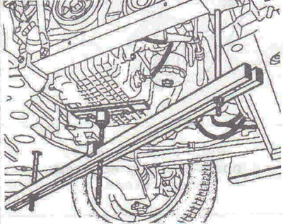
Figure 2.19. Install the engine support device Mot. 1367-02.
6. Move the upper part of tool 2 to the tray (figure 2.20). Adjust the position of section 2 on the pallet using clamps 3. Carefully lift the engine using bolt 4, then tighten nuts 5.
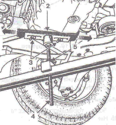
Figure 2.20. Move the upper part of tool 2 towards the tray. Adjust the position of section 2 on the pallet using clamps 3. Carefully lift the engine using bolt 4, then tighten nuts 5.
7. Unscrew the bolts 6 of the suspension arm, remove the engine suspension limiter, remove the auxiliary equipment drive belt (figure 2.21).
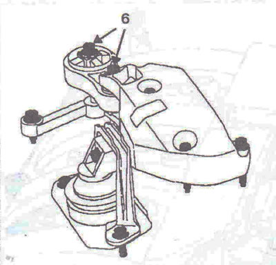
Figure 2.21. Unscrew bolts 6 of the suspension arm.
8. Disconnect the wiring connectors on the upper timing belt cover, the fuel line, and the gasoline vapor recovery tube from the middle timing belt cover.
9. Remove the air resonator.
10. Remove the camshaft oil seal plugs (figure 2.22).
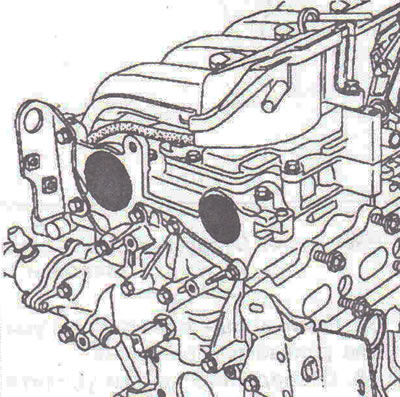
Figure 2.22. Remove the camshaft oil seal plugs.
11. Remove the plug from the TDC pin hole (figure 2.23).
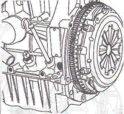
Figure 2.23. Remove the plug from the TDC pin hole.
Adjusting the valve timing
12. Turn the crankshaft clockwise so that the camshaft grooves are directed downwards and are located almost horizontally, as shown in Figure 2.24.
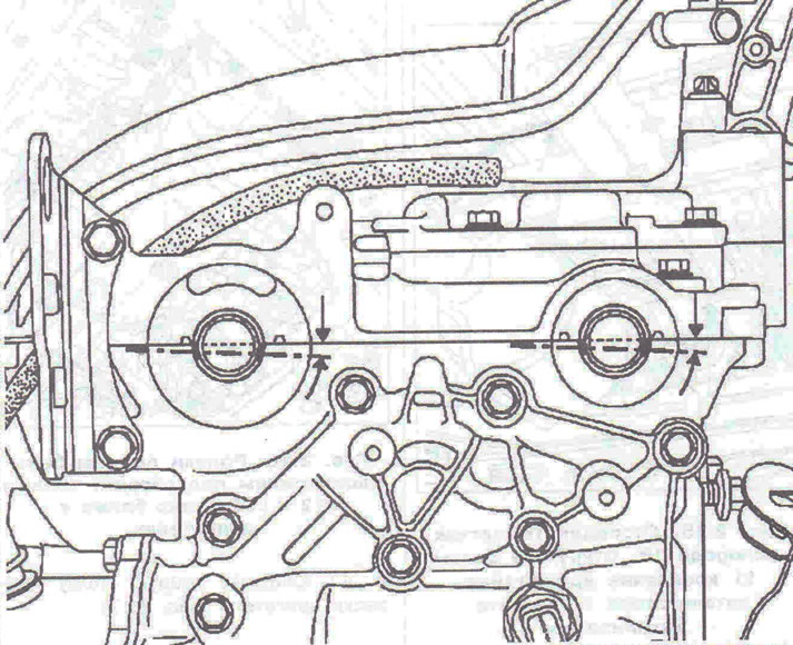
Figure 2.24. Rotate the crankshaft clockwise so that the camshaft grooves are facing downwards and are almost horizontal, as shown in the figure.
13. Insert TDC locking tool Mot. 1054 so that it is positioned between the balancing hole and the crankshaft groove (figure 2.25).
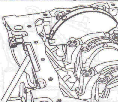
Figure 2.25. Insert TDC locking tool Mot. 1054 so that it is positioned between the balancing hole and the crankshaft groove.
14. Rotate the crankshaft in the same direction and insert the TDC locking pin into the installation point. The correct position of the TDC lock is shown in the figure 2.26, incorrect - in figure 2.27.
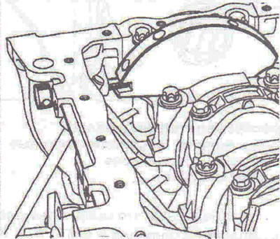
Figure 2.26. Correct position of the TDC lock.
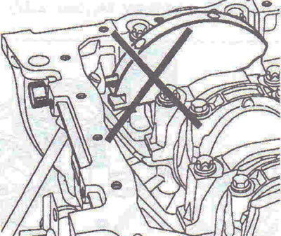
Figure 2.27. Incorrect position of the TDC lock.
15. The camshaft grooves, at the installation point, must occupy a horizontal position and be offset downwards relative to the axis, as shown in Figure 2.28.
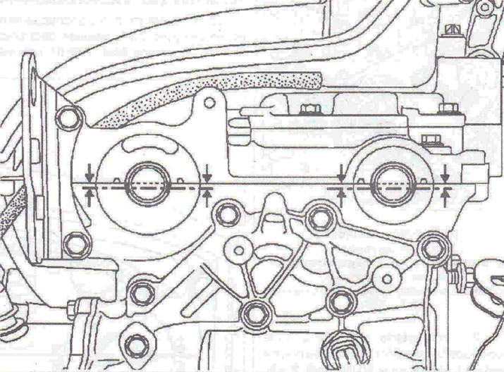
Figure 2.28. The camshaft grooves, at the installation point, must occupy a horizontal position and be offset downwards relative to the axis.
16. Turn the crankshaft and lock the flywheel with a screwdriver (figure 2.29).
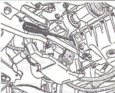
Figure 2.29. Turn the crankshaft and lock the flywheel with a screwdriver.
17. Remove the middle 7 and upper 8 parts of the timing belt cover (figure 2.30).
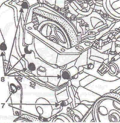
Figure 2.30. Remove the middle 7 and upper 8 parts of the timing belt cover.
18. Loosen the timing belt tension by loosening the 9 roller nut (figure 2.31). Remove roller 10 to avoid dropping the crankshaft toothed pulley (which does not have a key).
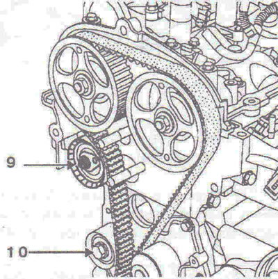
Figure 2.31. Loosen the timing belt tension by loosening nut 9 of the roller.
19. Remove the timing belt.
20. Remove the crankshaft toothed pulley.
Installation
First procedure
The first procedure is used when replacing all components that require loosening the camshaft pulleys.
21. Loosen the inlet and outlet camshaft pulleys using locking tool Mot. 1509 (figure 2.32).
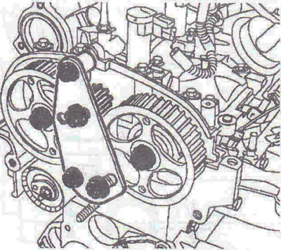
Figure 2.32. Loosen the inlet and outlet camshaft pulleys using locking tool Mot. 1509.
22. Fit the locking tool Mot. 1509 and tighten the nuts 11 to a torque of 80 Nm (figure 2.33).
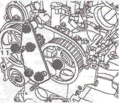
Figure 2.33. Fit the locking device Mot. 1509 and tighten the nuts 11.
23. Unscrew all nuts 12 securing the pulleys of the intake and exhaust camshafts (figure 2.34).
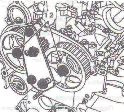
Figure 2.34. Unscrew all nuts 12 securing the pulleys of the intake and exhaust camshafts.
24. Remove the locking device Mot. 1509.
Setting the valve timing
25. Position the camshaft grooves horizontally as shown in Figure 2.35, rotating the camshafts using the Mot. 799-01 timing belt locking tool if necessary.
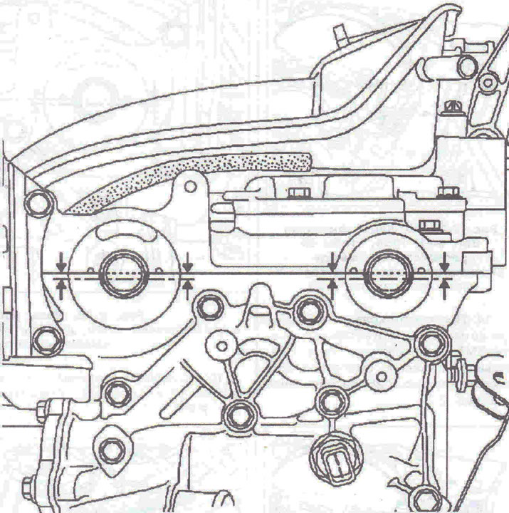
Figure 2.35. Position the camshaft grooves horizontally as shown in the figure, rotating the camshafts using the Mot. 799-01 timing belt locking tool if necessary.
26. Fit tool Mot. 1496 to the end of the camshafts (figure 2.36).
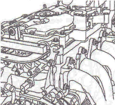
Figure 2.36. Fit tool Mot. 1496 to the end of the camshafts.
27. Replace the old pulley mounting nuts with new ones (leave a gap between the camshaft pulleys and nuts of 0.5-1 mm).
28. Make sure the crankshaft is correctly positioned at TDC.
29. The tension roller and idler roller must be replaced when replacing the timing belt.
30. Install the eye of the tension roller 13 into the groove 14 (figure 2.37).
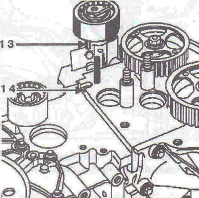
Figure 2.37. Install the eye of the tension roller 13 into the groove 14.
31. Install the timing belt and roller 15 (figure 2.38). Tighten the idler pulley mounting bolt to 50 Nm.
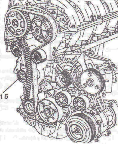
Figure 2.38. Install the timing belt and roller 15.
32. Install the lower part of the timing belt cover without tightening the bolts, and the crankshaft pulley, tightening the bolt by hand (without bolt locking, 2-3mm gap between bolt and pulley).
33. The bolt and pulley must be replaced.
Belt tension
34. Make sure that there is still a gap of 0.5-1 mm between the nuts and the camshaft pulleys.
35. Align marks 16 and 17 on the tension roller using a 6mm Allen key 18 (figure 2.39).
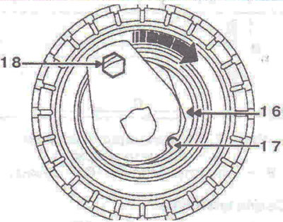
Figure 2.39. Align marks 16 and 17 on the tension roller using a 6 mm Allen key 18.
Note: Do not turn the tension roller counterclockwise.
36. Pre-tighten the tension roller nut to 7 Nm.
37. Turn the camshafts six turns using the exhaust camshaft pulley using tool Mot. 799-01.
Caution: Make sure the camshaft pulley nuts do not touch the pulleys. To do this, move the pulleys to the camshafts from time to time.
38. Align marks 16 and 17, if necessary loosening the tensioner roller nut no more than one turn, while holding the roller with a 6 mm Allen key.
39. Tighten the tension roller nut to 28 Nm.
40. Tighten the crankshaft pulley bolt to 20 Nm (the crankshaft is still locked by the TDC locking pin).
41. Make a mark 19 with a pencil between the camshaft pulleys and the camshaft housing (figure 2.40).
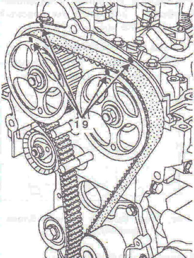
Figure 2.40. Make a mark 19 with a pencil between the camshaft pulleys and the camshaft housing.
42. Lock the flywheel with a large screwdriver, then tighten the crankshaft pulley bolt (40 Nm + 110° ±6°) (figure 2.41).
43. Lock the crankshaft using the previously made marks between the camshaft pulleys and the camshaft housing.
44. Check the alignment of the marks.
45. Fit the camshaft locking tool Mot. 1509 and tighten the nuts to a torque of 80 Nm.
46. Replace the old nuts with new ones.
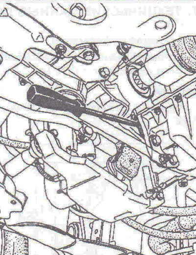
Figure 2.41. Lock the flywheel with a large screwdriver, then tighten the crankshaft pulley bolt.
47. Tighten the intake and exhaust camshaft pulley nuts to a torque of 30 Nm and tighten to an angle of 86° ±6°.
48. Remove tool Mot. 1509 for locking the camshaft pulley, TDC locking tool Mot. 1054, tool for correct installation of camshafts Mot. 1496.
Checking the belt tension and valve timing
Checking the belt tension
49. Rotate the crankshaft two turns clockwise (from the timing belt side).
50. Before the end of the second revolution, insert the TDC locking pin so that it is located between the balancing and measuring holes.
51. Align the valve timing points.
52. Remove the TDC lock.
53. Align the tension roller marks and tighten the tension roller nut to 28 Nm.
Second procedure
The second procedure is carried out when replacing all components that do not require loosening the camshaft pulleys.
Tightening torques
Crankshaft pulley bolt -40 Nm + 110° ±6°.
Camshaft pulley nuts - 30 Nm + 86° ±6°.
Tensioner pulley nut - 28 Nm.
Pulley mounting bolt - 50 Nm.
[Original source is on the website: www.opelbook.ru]
Visitor comments