
OpelBook.ru
Cars AvtoVAZ Cars Mitsubishi Cars BMW Cars Mercedes Cars Nissan Cars Toyota Cars Chevrolet
English Русский
Български
Беларускі
Український
Српски
Hrvatski
Română
Polski
Slovenský
Magyar
 |  Sitemap  |  Contacts  |    


Main Astra Corsa Insignia Kadett Omega Vectra Zafira Others Articles
Frontera A (1991-1998, petrol) Frontera B (1998-2004) Ascona C (1981-1988) Vivaro A (2001-2014)
  • Main
  • Opel
  • Vivaro A
  • Power unit
  • Petrol engine F4R
  • Removal and installation the engine

Removal and installation the engine (Opel Vivaro A)

            0

Contents: Removal ⬇ Installation ⬇

Removal


1. Place the vehicle on a two-post lift.

Caution: During this operation, secure the vehicle with a belt to avoid instability.


2. Remove the carpet under the left seat and the battery cover 1 (figure 2.3).
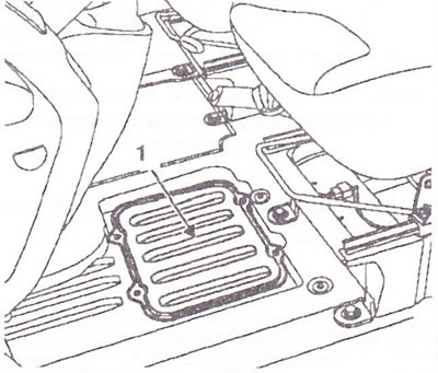
Figure 2.3. Remove the mat under the left seat and battery cover 1.

Figure 2.3. Remove the mat under the left seat and battery cover 1.


3. Disconnect the battery.

4. Remove the front wheels, engine sump, power wires, and ground wire from the body.

5. Set the power wires aside.

6. Drain the cooling system fluid through the lower radiator hose and drain the oil from the gearbox and engine if necessary.

Right side of the car


7. Remove the brake caliper and attach it to the suspension spring, ABS sensor, unscrew the lower ball joint nut (use a socket wrench with X = 22 mm if necessary to lock the ball joint), unscrew both bolts securing the gearbox flange to the bracket, remove the tie rod end using the T.Av. 476 tool and two shock absorber supports.

8. Disconnect the axle shaft.

9. Remove the hub together with the axle shaft.

Left side of the car


10. Remove the brake caliper and attach it to the suspension spring, ABS sensor, unscrew the lower ball joint nut (use a socket wrench with X = 22 mm if necessary to lock the ball joint), remove the tie rod end using the T.Av. 476 tool, the half-shaft protection supports and the two shock absorber supports.


11. Disconnect the axle shaft.

12. Remove the hub together with the axle shaft.

13. Remove the number plate, indicator lights and radiator grille (figure 2.4).
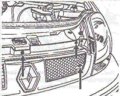
Figure 2.4. Remove the radiator grille.

Figure 2.4. Remove the radiator grille.


14. Unscrew the 2 headlight mounting bolts (figure 2.5).

15. Disconnect the wiring connectors from the headlight.
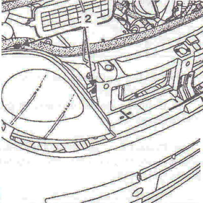
Figure 2.5. Unscrew the bolts 2 securing the headlight.

Figure 2.5. Unscrew the bolts 2 securing the headlight.


16. Remove the headlight by removing the clips 3 (figure 2.6).
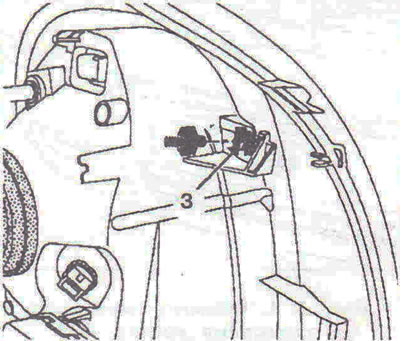
Figure 2.6. Remove the headlight by removing the fasteners 3.

Figure 2.6. Remove the headlight by removing the fasteners 3.


17. Remove the bumper (figure 2.7a, b).
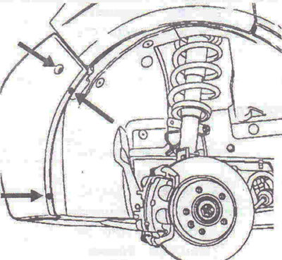
Figure 2.7a. Remove the bumper.
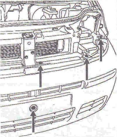
Figure 2.7a. Remove the bumper.


Figure 2.76. Remove the bumper.

Figure 2.76. Remove the bumper.


18. Remove the power steering fluid reservoir.

19. Remove the hood locking mechanism 4, disconnect the hood release cable (figure 2.8).
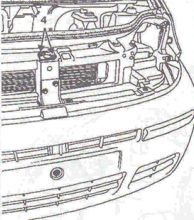
Figure 2.8. Remove the hood locking mechanism 4.

Figure 2.8. Remove the hood locking mechanism 4.


20. Remove the upper and lower radiator supports, radiator grille, radiator air ducts, air resonator.


21. Disconnect the wiring connectors from the fan and the wiring connector from the pressure sensor.

22. Disconnect the air conditioning system pipes from the compressor and condenser.

23. Disconnect the wiring connector from the fuel shut-off sensor 5 (figure 2.9).
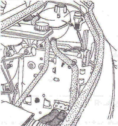
Figure 2.9. Disconnect the wiring connector from the fuel shut-off sensor 5.

Figure 2.9. Disconnect the wiring connector from the fuel shut-off sensor 5.


24. Remove the radiator, expansion tank and engine control unit protective plate.

25. Disconnect the wiring connector from the engine control unit.

26. Remove all fuse holders.

27. Disconnect the ground wire on the left side.

28. Remove the heater radiator pipes using Mot. 1448.
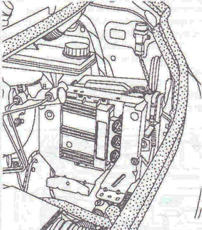
Figure 2.10. Disconnect the wiring connector from the engine control unit.

Figure 2.10. Disconnect the wiring connector from the engine control unit.


29. Disconnect vacuum pipe 6 from the brake booster (figure 2.11).
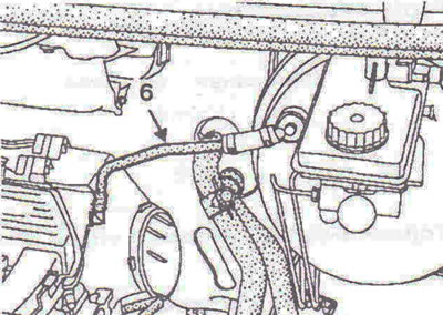


Figure 2.11. Disconnect vacuum pipe 6 from the brake booster.

Figure 2.11. Disconnect vacuum pipe 6 from the brake booster.


30. Disconnect the fuel intake line.

31. Remove the clutch slave cylinder retainer, the 7 pipe retainer and the gear shift and selection cables (figure 2.12).
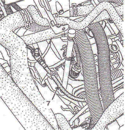
Figure 2.12. Remove clamp 7 of the clutch hydraulic drive line.

Figure 2.12. Remove clamp 7 of the clutch hydraulic drive line.


32. Disconnect the wiring connector 8 (figure 2.13).
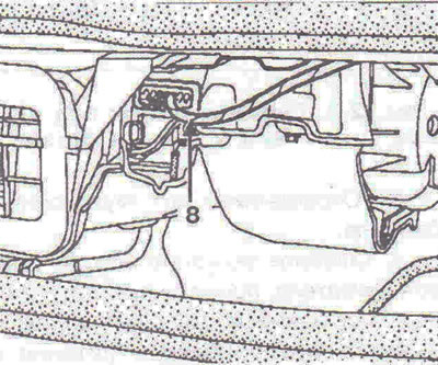
Figure 2.13. Disconnect wiring connector 8.

Figure 2.13. Disconnect wiring connector 8.


33. Remove the heater.

34. Remove the air filter.

35. Disconnect the gasoline vapor recovery pipe.

35. Disconnect the wiring connector from the throttle body.

36. Unscrew the two bolts 9 securing the throttle body and remove it (figure 2.14).
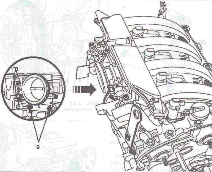
Figure 2.14. Unscrew the two bolts 9 securing the throttle body and remove it.

Figure 2.14. Unscrew the two bolts 9 securing the throttle body and remove it.


37. Drain the fluid from the power steering reservoir.

38. Disconnect the power steering pipes from the steering gear.

39. Disconnect the oxygen sensor 10 (figure 2.15). Unscrew bolts 11 securing the catalytic converter bracket and remove the catalytic converter.
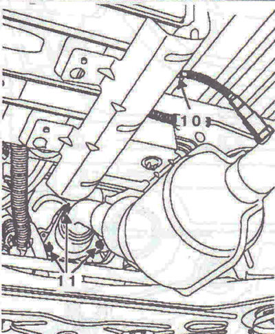
Figure 2.15. Disconnect oxygen sensor 10. Unscrew bolts 11 securing the catalytic converter bracket…

Figure 2.15. Disconnect oxygen sensor 10. Unscrew bolts 11 securing the catalytic converter bracket and remove the catalytic converter.


40. Disconnect the lower cross member and engine mount arms.

41. Fit the Mot. 1390 engine and gearbox support device under the engine.

42. The rollers should be located under the grey areas 12 and as close to the engine as possible (figure 2.16).
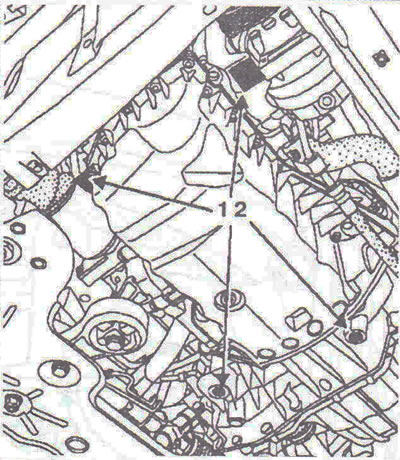
Figure 2.16. The rollers should be located under the grey areas 12 and as close to the engine as…

Figure 2.16. The rollers should be located under the grey areas 12 and as close to the engine as possible.


43. Remove the right engine mount support (figure 2.17).

Caution: Make sure the engine is mounted on the support device before completely loosening the bolts.


44. Unscrew nut 13 and hit it with a copper hammer (figure 2.18). Remove the rubber cushion and gearbox support.
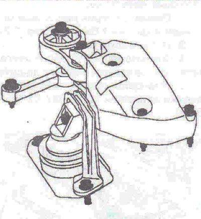
Figure 2.17. Remove the right engine mount support.
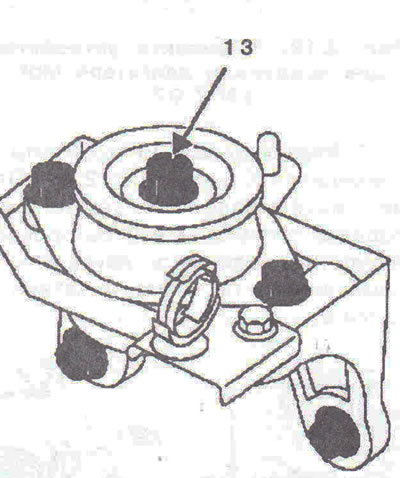
Figure 2.17. Remove the right engine mount support.


Figure 2.18. Unscrew nut 13.

Figure 2.18. Unscrew nut 13.


Installation


45. Installation is carried out in the reverse order of removal.

Tightening torques


  • Brake caliper bolt -35 Nm.
  • Shock absorber mounting bolt -180 Nm.
  • Steering rod ball joint mounting nut - 37 Nm.
  • Gearbox suspension nut -62 Nm.
  • Lower ball joint nut -110 Nm.
  • Engine pendulum mount bolt - 105 Nm.
  • Upper rod bolt of engine pendulum mount - 105 Nm.
  • Axle shaft protection bolt - 44 Nm.
  • Wheel mounting bolt - 140 Nm.


This article is available at russian, bulgarian, belarusian, ukrainian, serbian, croatian, romanian, polish, slovak, hungarian
Checking the article: Meshcheryakov Damir

Share information:

Previous articles
Opel Vivaro A: Petrol engine F4R
Next articles

Checking oil pressure
Volumes of working fluids
Adjusting the engine accessory drive belt
Tightening the cylinder head
Removal and installation the timing belt
Engine technical data
Technical characteristics of fuel injection system components
Removal and installation the throttle body
Removal and installation the intake manifold
Removal and installation the exhaust manifold


See similar ones from other Opel car manuals:
▶ Engine bay — 1.4L C 14 NZ engine Opel Astra F (1991-1998, petrol)
▶ Starting the engine from an auxiliary power source Opel Corsa B (1993-2000)
▶ Engine compartment fuse box Opel Insignia A (2008-2017)
▶ Engine hood Opel Kadett E (1984-1995)
▶ Starting the engine Opel Omega A (1986-1993)
Link to this page in different formats

Visitor comments


No comments yet


How much will 49 + 46 =


Vivaro A (2001-2014) 
  • General information
  • User manual
  • Power unit
  • Petrol engine F4R
  • Diesel engine F9Q
  • Diesel engine G9U
  • Transmission
  • Clutch and drive shafts
  • Manual gearbox
  • Chassis
  • Front suspension
  • Rear suspension
  • Brake system
  • Body
  • Exterior
  • Interior
  • Electrical equipment
  • Heating and ventilation
  • Air conditioner
  • Equipment and devices
  • Electrical diagrams
Ascona C (1981-1988) 
  • General information
  • Maintenance
  • Power unit
  • Gasoline engines
  • Diesel engines
  • Cooling system
  • Fuel and exhaust system
  • Contact ignition system
  • Contactless ignition system
  • Transmission
  • Clutch
  • Mechanical gearbox
  • Automatic gearbox
  • Drive shafts
  • Chassis
  • Steering
  • Brake system
  • Car suspension
  • Body
  • Exterior
  • Interior
  • Doors and windows
  • Electrical equipment
  • Equipment and devices
  • Power devices
  • Electrical circuits
Frontera B (1998-2004) 
  • General information
  • User manual
  • Maintenance
  • Power unit
  • Petrol engines 2.2 l
  • Petrol engines 3.2 l
  • Diesel engines 2.2 l
  • Cooling system
  • Fuel system (petrol)
  • Fuel system (diesel)
  • Ignition system
  • Transmission
  • Clutch
  • Manual gearbox MUA5C
  • Automatic gearbox 4L30E
  • Chassis
  • Suspension and axles
  • Steering
  • Brake system
  • Body
  • Exterior
  • Interior
  • Doors, locks and windows
  • Heating and air conditioning
  • Electrical equipment
  • Power devices
  • Equipment and devices
  • Lighting and signaling
  • Electrical diagrams
Frontera A (1991-1998, petrol) 
  • General information
  • Introduction to guide
  • User manual
  • Maintenance
  • Power unit
  • Engine repair
  • Lubrication system
  • Cooling system
  • Power and exhaust system
  • Engine electrics
  • Transmission
  • Clutch
  • Mechanical gearbox
  • Cardan shafts
  • Chassis
  • Brake system
  • Front suspension
  • Rear suspension
  • Steering
  • Body
  • Repair and care
  • Electrical equipment
  • Equipment and devices
  • Electrical circuits
OpelBook.ru © 2017–2026 · Mobile version · · Sitemap: EN BG BY UA RS HR RO PL SK HU · Feedback · Site search
Astra F, petrol · Astra G, petrol · Astra G · Astra H · Astra J, petrol · Corsa B · Corsa C, petrol · Corsa C · Insignia A · Kadett D · Kadett E · Omega A · Omega B · Omega B2 · Vectra A, petrol · Vectra A · Vectra B, petrol · Vectra B · Vectra C · Zafira A, petrol · Frontera A, petrol · Frontera B · Ascona C · Vivaro A ·
We want your visit to be comfortable 🤝! We use cookies 🍪 to make that happen.