
Signs of a bad cylinder head gasket are: loss of power, loss of coolant, loss of oil, or presence of coolant in the engine oil.
In addition, a defective head gasket is determined by the presence of bubbles in the coolant. To do this, remove the cap from the expansion tank and start the engine. Bubbling coolant is a sign of a defective cylinder head gasket.
Removing
Attention: Remove the head on a cold engine (at room temperature approximately 20°C).
Disconnect the earth cable from the battery.
Remove the air filter with heating hose, see paragraph 4.44.
Remove the exhaust manifold from the cylinder head, press it out and tie it down.
Drain the coolant into a container of suitable size, see point 3.2.
Remove the coolant drain plug on the cylinder block.
Attention: Immediately after draining, coat the plug with sealant (e.g. Curil), screw in and tighten.
Mark and remove all cable drives and electric males from the carburetor.
Remove carburetor.
Remove intake pipe.
Remove the upper and lower coolant hoses from the thermostat housing and water pump.
Remove heater hoses at coolant pump and cylinder head.
Loosen alternator tensioner and remove V-belt.
Remove cylinder head cover.
Loosen the rocker nuts so that the push rods can be removed.
Attention: Before removing the cylinder head, it is imperative to remove the push rods, because they may fall into the oil pan.
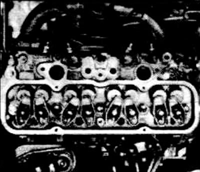
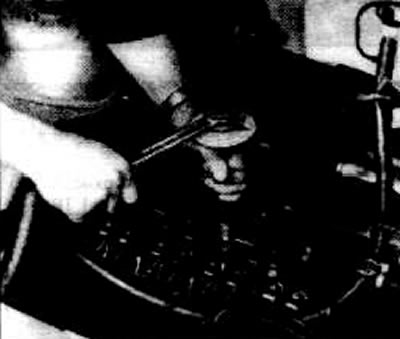
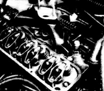
Release cylinder head bolts in a spiral from inside to outside, see illustration. First loosen all bolts 1/2 turn, then back out completely.
Remove bolts.
Remove the cylinder head.
Installation
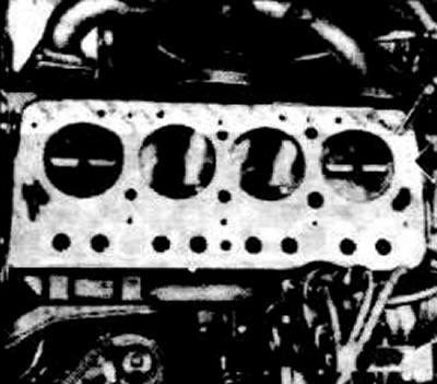
Clean mating surfaces of block and cylinder head.
Check the evenness of the surface of the cylinder block, see paragraph 1.20.
Check the flatness of the surface of the cylinder head, see paragraph 1.19.
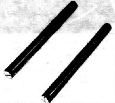
Make two guide rods (cut-off cylinder head bolts), see picture.
Screw the guide rods into the cylinder block.
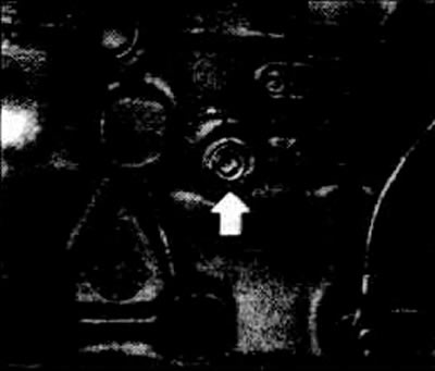
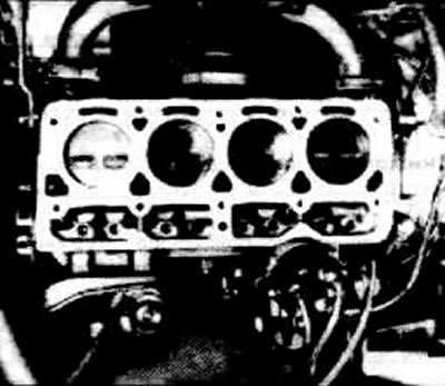
Apply a new cylinder head gasket without sealant, while paying attention to the mark "Oben" (top), see the arrow in the illustration.
Install the cylinder head.
Tighten the cylinder head bolts by hand until the bolt heads are in contact.
Caution: Use new cylinder head bolts for every repair.
Remove guide rods and replace with cylinder head bolts.
Tighten the head bolts in a spiral pattern from the inside to the outside to 25 Nm, see section «Withdrawal».
Then tighten the cylinder head bolts in three passes in a spiral from inside to outside.
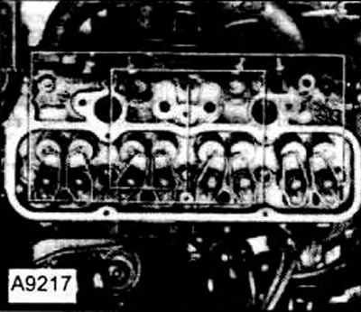
On the second pass, tighten the bolts with a wrench by 60°in a spiral from the inside to the outside, see drawing A9217.
On the third pass - another 60°in a spiral. Mark the 60°mark on the cylinder head cover in advance. To do this, put the key on the bolt and make a mark at an angle of 60°.
On the fourth pass, tighten the bolts in a spiral by another 60°.
Attention: Further tightening after 1000 km is not required.
Insert lubricated push rods.
Install the rocker arm and tighten the nut by hand.
Attention: After installing the cylinder head, adjust the valves on a cold engine.
Valve clearances: inlet 0.15 to you outlet 0.25 mm.
Adjust valve clearances. To do this, set the piston of the 1st cylinder to TDC.
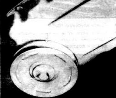
The piston of the first cylinder will be at TDC when the convex mark on the timing cover is opposite the spline on the crankshaft pulley, and if the ignition distributor slider points to the mark on the ignition distributor housing.
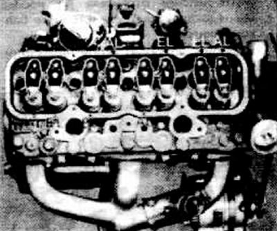
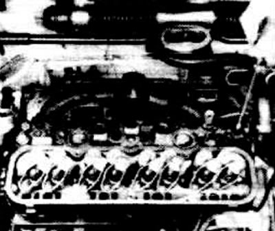
The location of the valves can be seen in the figure.
If the piston of the 1st cylinder is in the 8th ignition position, the following valves can be adjusted:
- 1st cylinder - inlet and outlet valve
- 2nd cylinder - intake valve 3rd cylinder - exhaust valve.
Check the valve clearance with a suitable feeler gauge. The probe should hardly move between the rocker arm and the end of the valve stem. Otherwise, adjust the gap, see paragraph 1.18.
Rotate the crankshaft a full turn (360°) with a wrench, behind the crankshaft pulley.
Now you can check and adjust the clearance of the following valves:
Set valve clearance:
- 4th cylinder - intake and exhaust valve
- 3rd cylinder - inlet valve
- 2nd cylinder - exhaust valve
Attention: After adjustment, check the valve clearances again with a warm engine and, if necessary, adjust, see paragraph 1.18.
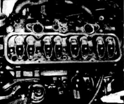
Screw on the intake manifold with a new gasket and tighten to 23 Nm.
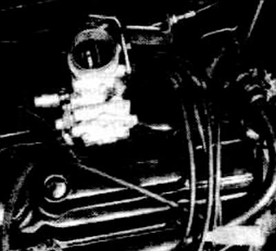
Attention: Pay attention to the holder of the ignition wires, see the arrow in the figure.
Screw the exhaust manifold with a new gasket to the cylinder head and tighten the bolts to 23 Nm.
Screw the exhaust pipe holder to the rear engine support.
Install and tighten the timing cover with a new gasket.
Fit the carburetor with a new gasket and tighten to 18 Nm.
Connect all electrical wires to the carburetor.
Install without tension all cable drives, see point 4.
Connect the ignition cable.
Put on and tighten the V-belt, see point 22.2.
Connect the upper and lower coolant hoses to the thermostat housing and water pump housing.
Connect the heater hose to the water pump.
Pour coolant through the expansion tank until it comes out of the heater hose fitting, see point 3.2.
Attach the air filter see paragraph 4.44.
Connect ground cable to battery.
Start the engine and check the tightness of the seals.
Attention: Once again check the valve clearance with a warm engine, see paragraph 1.18.
Visitor comments