
Note. If possible, work on a special turntable that provides access to the engine from all sides, since it is very difficult to fix the engine from moving when unscrewing fasteners tightened with a large torque.
1. Remove the power unit from the vehicle (see Removal and installation of the power unit).
2. Remove the starter (see Removal and installation of a starter).
3. Remove generator (see Removal and installation of the generator).
4. Disconnect the gearbox from the engine by unscrewing the bolts of its fastening to the engine (see Removal and installation of a transmission).
5. Remove the clutch from the flywheel (see Removal and installation of clutch).
6. Remove the flywheel (see Removal, troubleshooting and installation of the flywheel).
7. Remove the cylinder head (see Replacing the cylinder head gasket).
8. Remove the water pump (see Water pump replacement).
9. Remove the oil filter (see Changing engine oil and oil filter).
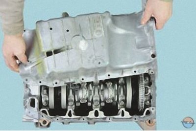
10. Remove the oil pan (see Replacing the oil sump seal).
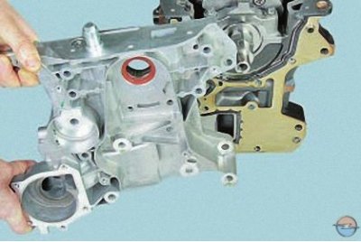
11. Remove the oil pump..
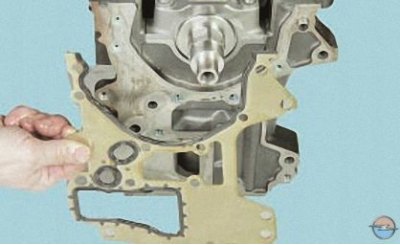
12.... and a sealing gasket installed under the flange of the oil pump housing (see Removal and installation of the oil pump).
Note. When disassembling the crank mechanism and the piston group, mark the pistons, connecting rods, as well as the liners of the main and connecting rod bearings in order to install them in their original places during assembly, if they are operational.
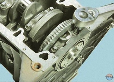
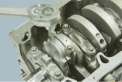
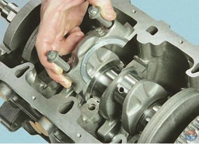
13. Turn out two bolts of fastening of a cover of the back radical bearing of a cranked shaft …
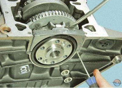
14.... slide the cover up..
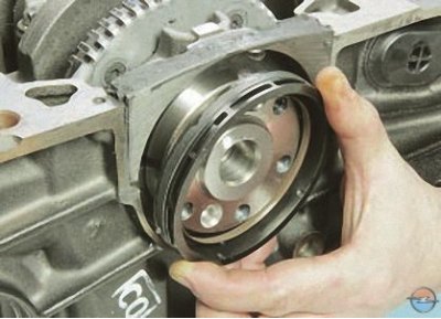
15.... remove the crankshaft rear oil seal from the cylinder block socket..
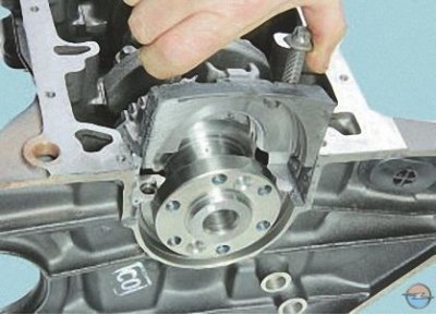
16.... and remove the crankshaft rear main bearing cover
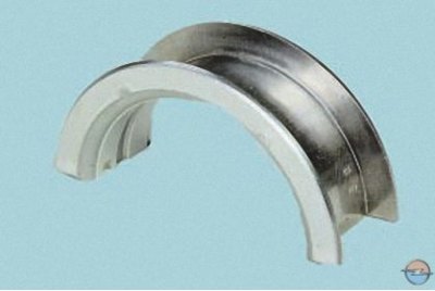
Note. Replace the rear oil seal with a new one each time you remove it.
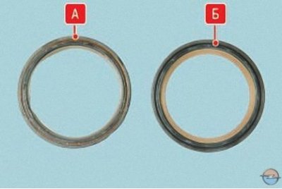
The photo shows the oil seal removed from the engine A and a new seal B. Diameter of the working surface of the stuffing box A increased, so when reinstalled, the oil seal will not seal the rear flange of the crankshaft.
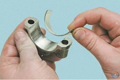
17. Turn out two bolts of fastening of a cover of a rod of the 1st cylinder, move a cover from a seat easy blows of a hammer through a wooden spacer …
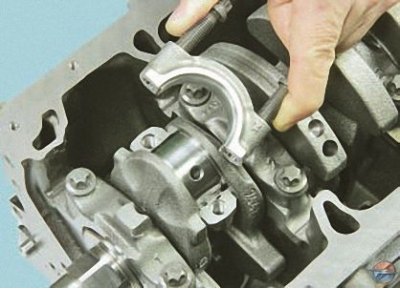
18.... and remove the cover with the insert.
Attention! The connecting rod and cap are not marked with cylinder numbers. Be sure to tag them in any way you can (for example, punching), in order to install them in their original places during assembly, since the connecting rod caps are interchangeable (connecting rod machined together with cover).
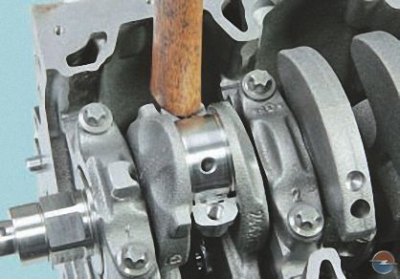
19. Press with a wooden block (hammer handle) on the rod...
20.... and remove the piston with the connecting rod from the cylinder towards the upper surface of the cylinder block.
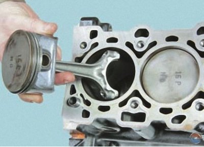
21. Similarly, remove the pistons and connecting rods of the remaining cylinders, turning the crankshaft to access the connecting rod cap bolts.
Note. Turn the crankshaft with a wrench by the flat on the front end.
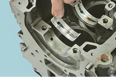
22. Turn out two bolts of fastening of any cover of the radical bearing. Separate the cover from the seat with light hammer blows through the wooden spacer..
23.... and remove the cover with the bottom liner.
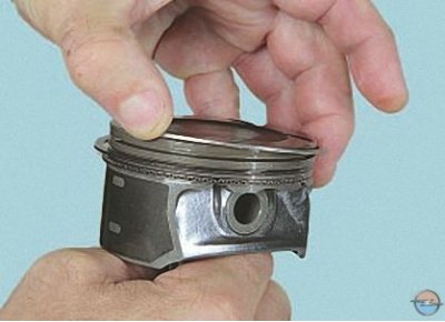
Attention! Main bearing caps are designed for one specific cylinder block only (covers are processed together with the block). The covers are not interchangeable with each other.
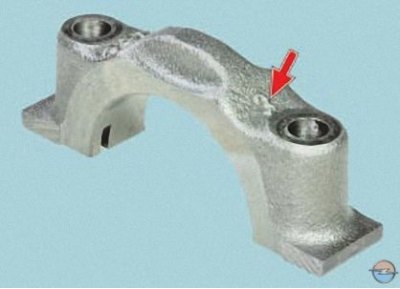
Covers are numbered according to the order in which they were installed (counting from the front of the engine).
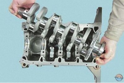
24. Turn out bolts, remove other covers of radical bearings and take a cranked shaft.
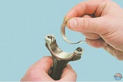
25. Remove the liners from all connecting rods...
26....and out of their caps..
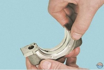
27.... from the main bearing caps..
28.... and from all the beds in the cylinder block.
Note. The cover insert of the third main bearing of increased thickness, along its side ends, beads are made, playing the role of thrust semi-rings that limit the axial movement of the crankshaft. Similar collars are made on the upper shell of the third main bearing.
29. Unclench the top compression ring..
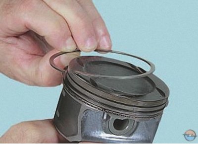
30.... and take it off.
31. Similarly, remove the second (bottom) compression ring.
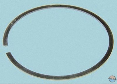
32. Unclench and remove the upper ring, expander and lower ring of the composite oil scraper ring
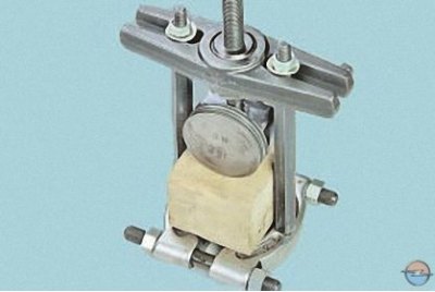
33. Using a screw or hydraulic press, press the piston pin out of the upper head of the connecting rod.
34. Take out a finger from the piston and remove the piston from a rod.
Note. Mark the details. If they are not damaged and slightly worn, they can be used by installing them in their original places.
Visitor comments