
- the pressure in the engine lubrication system has dropped. The cause of this malfunction is often increased wear on the camshaft journals and camshaft bearing beds in the cylinder head. When the beds and their covers are worn out, the block head is replaced as an assembly, since the beds are made directly in its body;
- valve knock at normal clearances in the valve drive mechanism. Caused by increased wear of the camshaft cams due to the use of poor quality engine oil or as a result of a damaged oil filter.
You will need: socket TORX E14, extension, wrench, keys «at 24» and TORX T55.
1. Disconnect the wire from the terminal «minus» battery.
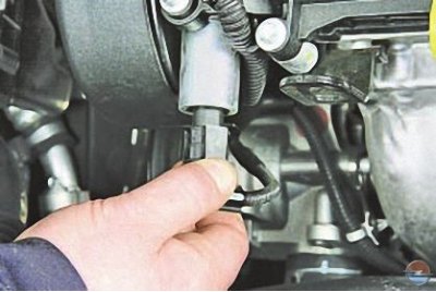
2. Press the latch..
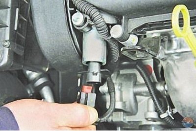
3.... and disconnect the wiring harness connector from the electro-hydraulic valve of the exhaust camshaft.
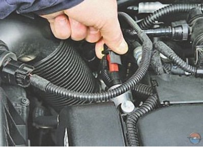
4. Disconnect the harness connector from the electro-hydraulic valve of the intake camshaft in the same way.
5. Remove the timing belt from the camshaft pulleys (see Replacing the timing belt).
6. Remove the cylinder head cover (see Replacing the cylinder head cover gasket).
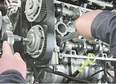
7. Holding the exhaust camshaft from turning with a key, unscrew the plug of the toothed pulley bolt..
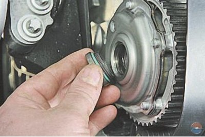
8.... and remove the plug.
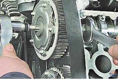
9. Unscrew and remove the intake camshaft plug in the same way.
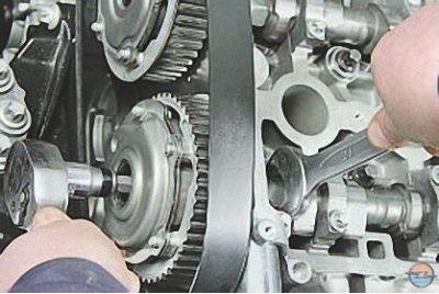
10. While holding the exhaust camshaft from turning, remove the toothed pulley mounting bolt..
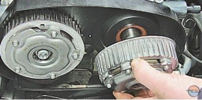
11.... and remove the pulley.
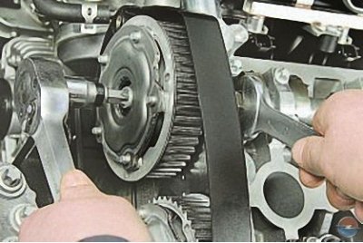
12. Similarly turn out a bolt and remove a gear pulley of a camshaft of inlet valves.
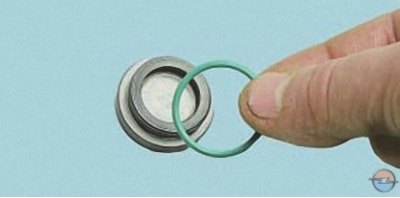
13. Replace sealing gaskets of caps of bolts of fastening of gear pulleys of camshafts irrespective of their condition.
14. Remove the right suspension bracket of the power unit (see Replacement of the right support of a suspension bracket of the power unit)
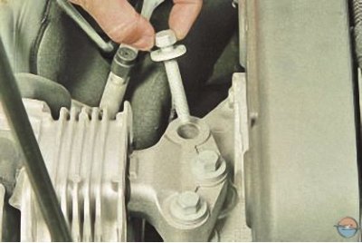
15. Turn out bolts of fastening of an arm of the engine to the block of cylinders and remove an arm.
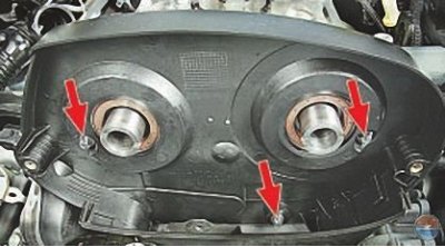
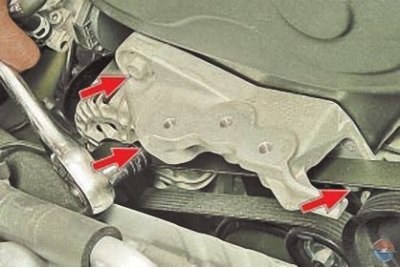
16. Turn out three top bolts …
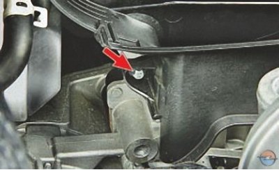
17.... and one lower bolt for fastening the upper cover of the timing gear.
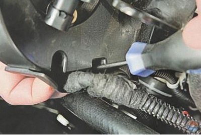
18. Overcoming resistance of clamps, disconnect the holder of a plait of wires from the top casing.
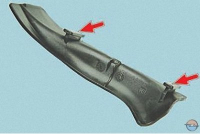
Note. This is how the wire harness holder fasteners are located.
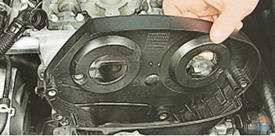
19. Remove the upper drive belt cover.
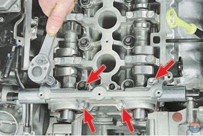
20. Turn out bolts of fastening of a forward cover of bearings of camshafts to a head of the block of cylinders …
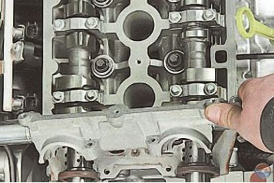
21.... and remove the cover.
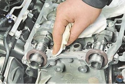
22. Clean the mating surfaces of the cylinder head..
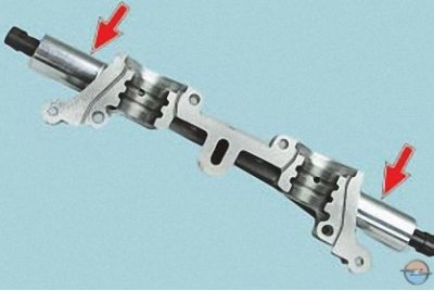
23.... and the front cover of the camshaft bearings.
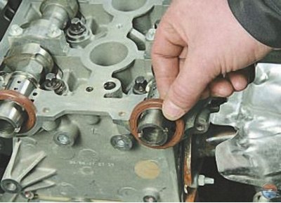
24. Remove the inlet and outlet camshaft seals from the sockets in the cylinder head.
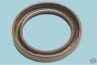
25. Replace the camshaft seals regardless of their condition.
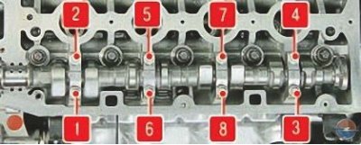
Pic. 1. The sequence of turning out the bolts of the camshaft bearing caps
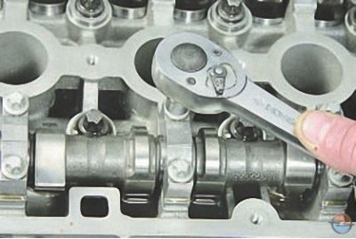
26. Loosen the bolts of the exhaust camshaft bearing caps in the sequence shown in fig. 1.
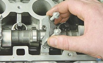
27. Completely unscrew the bolts, remove the camshaft bearing caps..
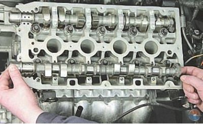
28.... and remove the exhaust camshaft.
29. Similarly, in the sequence indicated on rice. 1, unscrew the bolts securing the intake camshaft covers, remove the covers..
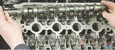
30.... and then the intake camshaft.
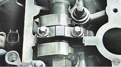
Attention! The camshaft bearing caps are processed together with the beds in the cylinder head, so they cannot be depersonalized. Bearing serial numbers are stamped on the covers. Cast numbers are technological for the lid casting process and do not serve as a guideline for lid installation. Install the camshaft bearing caps in strict accordance with the markings on them.
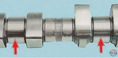
31. Inspect the camshafts. Bearing surfaces..
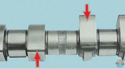
32.... and cams should be well polished and without damage. On the working surfaces of the necks, scoring, nicks, scratches, aluminum enveloping from the bearing seats in the block head are not allowed.
If there are signs of seizing, overheating, deep scratches or wear in the form of a cut on the working surfaces of the cams, replace the shafts.
Attention! Grinding of camshaft cams to eliminate stepped wear is prohibited, since when changing the size of the cam profile, the valve timing will be violated.
33. In workshops equipped with special tools and fixtures, you can check the radial runout of the camshaft journals. If the runout value is more than 0.02 mm or if the journals are misaligned, replace the shaft, since it cannot be edited.
34. Lubricate the beds of the camshafts with clean engine oil and lay the camshafts in them.
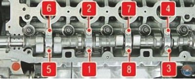
Pic. 2. The sequence of screwing in the bolts of the camshaft bearing caps
35. Establish covers of bearings of camshafts and evenly tighten bolts of their fastening, passing from a bolt to a bolt through a turn, in the sequence specified in fig. 2, moment.
36. Press the seals of the exhaust and intake camshafts into the sockets of the cylinder head (see Replacing camshaft seals).
37. Adjust the valve clearance (see Valve clearance adjustment).
38. Install the rest of the removed parts in the reverse order of removal.
Visitor comments