
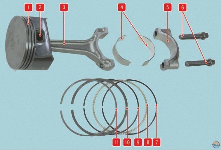
Pic. 1. Details of the connecting rod and piston group: 1 - piston; 2 - piston pin; 3 - connecting rod; 4 - liners; 5 – connecting rod cover; 6 – bolts of fastening of a cover of a rod; 7, 9 - oil scraper rings; 8 - oil scraper ring expander; 10 - lower compression ring; 11 - top compression ring
You will need: portable lamp, a set of flat probes, a ruler, a caliper, a caliper, a micrometer, a scraper.
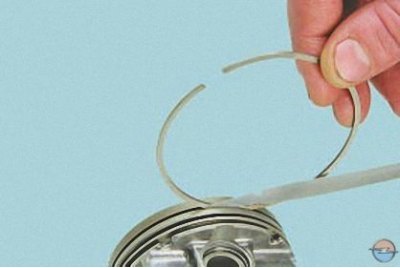
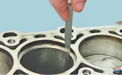
1. Clean the piston head from carbon deposits. If the piston has scuff marks, traces of burnout, deep scratches, cracks, replace the piston. Clean the grooves for the piston rings. It is convenient to do this with a piece of the old ring.
2. Using a suitable piece of wire, clean the oil drain holes in the piston.
3. Check up on the piston backlashes between rings and flutes, preliminary having cleared rings of a deposit. The gaps should be as follows:
- 0.04–0.075 mm for top compression ring;
- 0.03–0.07 mm for lower compression ring;
- 0.03–0.13 mm for the oil scraper ring.
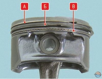
So the rings are located on the piston: A - the upper compression ring; B - lower compression ring; B - oil scraper ring.
4. The most accurate gaps can be determined by measuring the rings and grooves on the piston. To do this, measure the thickness of the rings with a micrometer in several places around the circumference, then use a set of feeler gauges to measure the width of the grooves also in several places around the circumference. Calculate Average Clearances (difference between ring thickness and groove width). If at least one of the gaps exceeds the maximum allowable value, replace the piston with rings.
5. Inspect the cylinders on both sides. Scratches, scuffs and cracks are not allowed.
Note. When inspecting, we recommend that you illuminate the mirrors of the cylinders with a portable lamp, so defects can be seen much better.
6. Measure the gaps in the locks of the rings by inserting the ring into a special mandrel. If there is no mandrel, insert the ring into the cylinder in which it worked (or will it work if the ring is new), move the piston like a mandrel into the cylinder so that it is installed in the cylinder evenly, without distortions and measure the gap in the ring lock with a feeler gauge.
The gaps in the locks of the rings should be as follows:
- 0.25–0.50 mm for top and bottom compression rings;
- 0.25–0.75 mm for the oil scraper ring.
Note. In order to install the ring without distortion, move it deep into the cylinder with the piston.
7. Measure the cylinder diameter in two mutually perpendicular planes (X - along, Y - across the cylinder block) and three belts (A, B and IN), as shown in fig. 2. For this, a special device is needed - a caliper. The nominal dimensions of the cylinders are given in table. 1. Ovality should not exceed 0.015 mm, taper - 0.01 mm. If the maximum wear value is greater than 0.2 mm, or the ovality and taper are greater than the specified values, bore the cylinders to the nearest oversize of the pistons, leaving an allowance of 0.03 mm for the honing diameter. Then honing the cylinders, maintaining such a diameter that when installing the piston, the estimated clearance between it and the cylinder was 0.03–0.05 mm. Troubleshooting, boring and honing of the block should be carried out in workshops with special equipment.
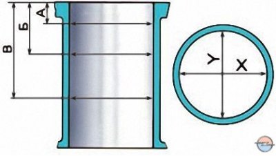
Pic. 2. Cylinder measurement scheme
Tab. 1. Dimensions of cylinders and pistons of the A16 XER engine
| Class | Cylinder diameter, mm | Piston diameter, mm |
| Nominal dimensions | ||
| 00 | 78,992–79,008 | 78,833–78,847 |
| 05 | 79,042–79,058 | 78,883–78,997 |
| Repair size | ||
| 00+0,5 | 79,492–75,508 | 79,433–79,447 |
8. Check up a deviation from flatness of a surface of a socket of the block with a head of the block of cylinders. Attach a caliper (or ruler) to the surface:
- in longitudinal and transverse directions;
- along the diagonals of the surface.
At each position, use a feeler gauge to determine the gap between the ruler and the surface. This is the deviation from flatness. If the deviation is greater than 0.1 mm, replace the block.
9. Check up backlashes between pistons and cylinders. The gap, determined by the difference between the measured diameters of the cylinder and piston, should be in the range of 0.03–0.05 mm.
If the gap does not exceed the maximum allowable, pistons from the following class can be selected so that the gap is as close to the nominal as possible. If the gap exceeds the maximum allowable, bore the cylinders and install oversized pistons.
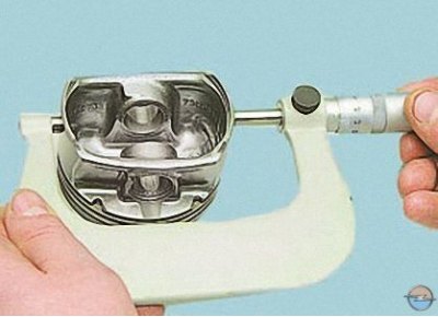
Measure the piston diameter at a distance of 19 mm from the bottom edge of the piston skirt in a plane perpendicular to the piston pin.
10. When replacing parts of the connecting rod and piston group, it is necessary to select pistons for cylinders by class and one group by weight, piston pins for pistons by class and connecting rods by weight. To match pistons to cylinders, calculate the gap between them. For the convenience of selecting pistons for cylinders, they are divided into two classes depending on the diameters (through 0.05 mm): 00, 05 (see table. 1).
Spare parts are supplied with pistons of a nominal size of two classes and a repair size increased by 0.5 mm.
For pistons of repair dimensions, spare parts are supplied with rings of repair dimensions increased by 0.5 mm.
11. Replace cracked piston pins. The finger should easily enter the piston with the force of the thumb. Insert your finger into the piston. If play is felt when shaking the finger, replace the piston. When replacing the piston, pick up a finger along the gap to it. To do this, measure the diameters of the holes in the piston bosses..
12.... and piston pin diameter. Calculate the gap as the difference between the diameters of the holes and the pin. The clearance between the piston pin and the holes in the piston should be 0.009–0.015 mm.
13. Replace broken rings and oil ring expander.
14. Replace rods if they are deformed.
15. Replace the connecting rod if, when disassembling the engine, it is found that the connecting rod bearings have turned in the connecting rod.
Attention! The connecting rods are processed together with the covers, so they cannot be dismantled.
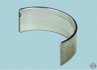
16. Inspect the liners. If risks, scuffing and delamination of the anti-friction layer are found on their working surface, replace the liners with new ones. All connecting rod bearings are identical and interchangeable.
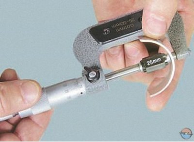
17. Measure the thickness of the connecting rod bearings with a micrometer (tab. 2).
Tab. 2. Parameters of the connecting rod bearings of the A16 XER engine
| Earbud size | Thickness, mm | Color marking | Code |
| Nominal | 1,485–1,497 | – | 264 N |
| 1st repair | 1,610–1,622 | Blue | 265 A |
| 2nd repair | 1,735–1,747 | White | 266 B |
On the end surface of the connecting rod bearings of repair dimensions, color marking is applied..
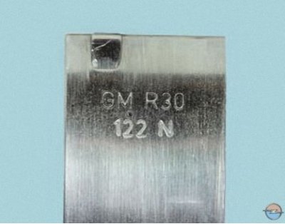
... and a code is applied to the non-working surface of all liners.
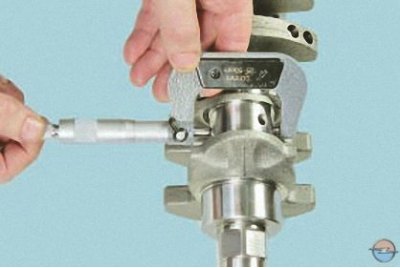
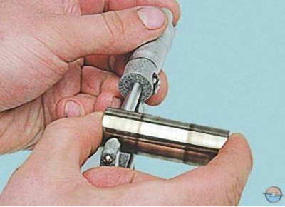
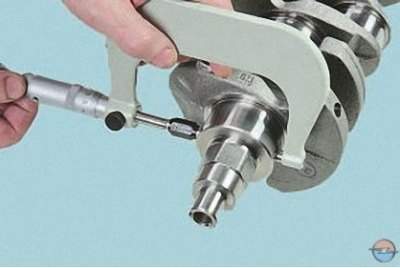
18. Measure the diameter Dn of the connecting rod journals of the crankshaft with a micrometer.
The diameters of the connecting rod journals of the crankshaft are indicated in Table. 3.
Tab. 3. Diameters of the connecting rod journals of the crankshafts of the A16 XER engine
| Neck size | Diameter, mm | Color marking |
| Nominal | 42,971–42,987 | – |
| 1st repair | 42,721–42,737 | Blue |
| 2nd repair | 42,471–42,487 | White |
19. Establish loose leaves in a rod and its cover, tighten bolts of fastening of a cover the moment of 25 Н·м and consistently tighten bolts at first on 30°, and then on 15°.
20. Measure the diameter with a caliper Dp connecting rod bearing at three locations across the shell width and determine the average diameter of the connecting rod bearing.
21. Calculate the connecting rod bearing clearance as the difference Dp and Dн. The allowable clearance of the connecting rod bearing is 0.019–0.071 mm.
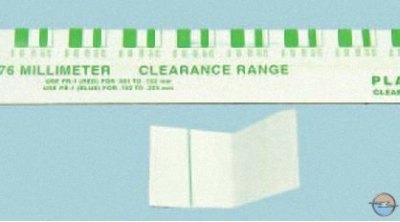
Note. The most accurate connecting rod bearing clearance can be determined using a special deformable Plastigage synthetic fiber strip. The Plastigage kit consists of a set of several strips and a scale.
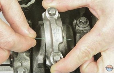
22. To measure the connecting rod bearing clearance using the Plastigage gauge wire, place a piece of wire on the crankshaft journal, lubricate the connecting rod bearings with engine oil, and install the connecting rod on the crankshaft journal.
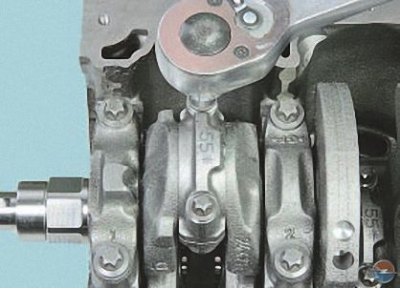
23. Tighten the cover fastening bolts to a torque of 25 Nm and tighten the bolts sequentially, first by 30°, and then by 15°. In this case, the connecting rod must not be rotated relative to the crankshaft (if measurements are taken on a removed shaft) or rotate the crankshaft (if the shaft is installed in the engine).
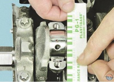
24. Remove the connecting rod cover and compare the width of the deformed wire with the scale divisions. The value of each division of the scale corresponds to a certain clearance in the bearing.
If the actual clearance is less than the limit, you can reuse the liners that were installed.
If the gap is greater than the maximum allowable, you can replace the liners on these necks with new ones of a nominal thickness of a suitable class.
If the crankshaft journals are worn and ground to repair size, replace the liners with repair ones (increased thickness).
The necks are ground, in addition to the presence of general wear, if they have nicks and risks, or if the ovality and taper are more than 0.005 mm.
25. Measure the thickness of the main bearings with a micrometer (tab. 4).
Tab. 4. Parameters of the main bearings of the A16 XER engine
| Earbud size | Thickness, mm | Color marking | Code |
| 1st, 2nd, 4th and 5th bearings | |||
| Nominal | 1,987–1,993 1,993–1,999 | brown Green | 256 N 257 N |
| 1st repair | 2,112–2,118 2,118–2,124 | Brown/blue Green/blue | 258 A 259 A |
| 2nd repair | 2,237–2,243 2,243–2,249 | Brown/White Green/White | 260 B 261 B |
| 3rd bearing | |||
| Nominal | 1,987–1,993 1,993–1,999 | brown Green | 859 N 860 N |
| 1st repair | 2,112–2,118 2,118–2,124 | Brown/blue Green/blue | 861 A 862 A |
| 2nd repair | 2,237–2,243 2,243–2,249 | Brown/White Green/White | 863 B 864 B |
26. Measure the diameter with a micrometer Dн crankshaft journals (tab. 5). The actual clearance between the main bearing shells and the crankshaft main journals is determined by the methods described for connecting rod bearings. The allowable crankshaft main bearing clearance is 0.005–0.059 mm.
Tab. 5. Diameters of the main journals of the crankshaft of the A16 XER engine
| Neck size | Diameter, mm | Color marking |
| Nominal | 54,980–54,997 | Brown, green |
| 1st repair | 54,730–54,747 | Brown, green |
| 2nd repair | 54,482–54,495 | Brown, green |
If the actual design gap is less than the maximum allowable, you can reuse the liners that were installed.
If the gap is greater than the maximum allowable, you can replace the liners on these necks with new ones of a nominal thickness of a suitable class.
If the crankshaft journals are worn and ground to repair size, replace the liners with repair ones (increased thickness).
Attention! When regrinding the connecting rod and main journals of the crankshaft to the repair size, it is necessary to put an appropriate stamp on the first cheek of the crankshaft, for example «W 0.25» And «K 0.25» respectively.
Visitor comments