
A leak can also occur due to warping of the block head due to overheating.
You will need: the same tools as for removing the timing belt (see Replacing the timing belt), camshafts of the gas distribution mechanism (see Removal, troubleshooting and installation of camshafts) and cylinder head covers (see Replacing the cylinder head cover gasket).
1. Reduce the pressure in the supply system (see Reducing the pressure in the power system).
2. Disconnect the wire from the terminal «minus» battery.
3. Drain the liquid from the cooling system (see Coolant replacement).
4. Remove the timing belt from the camshaft pulleys (see Replacing the timing belt).
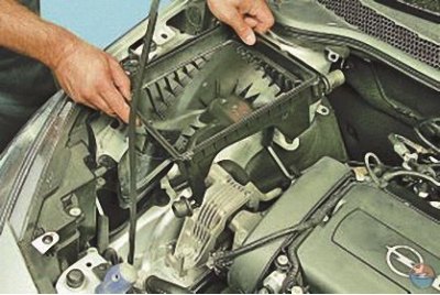
5. Remove the air filter and air duct (see Removal and installation of the air filter, air duct and intake silencer).
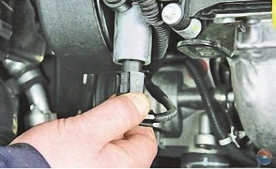
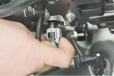
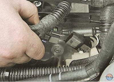
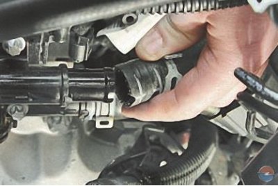
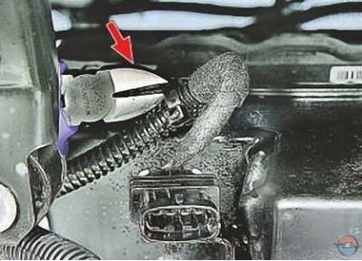
6. Press the latch..
7.... and disconnect the wiring harness block from the electro-hydraulic valve of the exhaust camshaft.
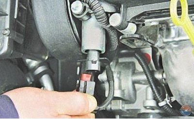
8. In the same way, disconnect the wiring harness block from the electro-hydraulic valve of the intake camshaft.
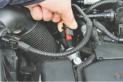
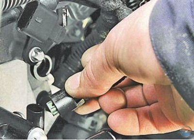
9. Press the latch..
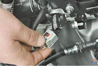
10.... and disconnect the wiring harness block from the coolant temperature sensor.
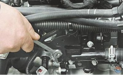
11. Turn away a nut of fastening of an arm of a motor plait of wires …
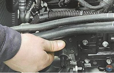
12.... remove the bracket from the stud and move the wiring harness to the side.
13. Disconnect the wiring harness connector from the intake camshaft position sensor.
14. Similarly disconnect block of a plait of wires from the gauge of position of a camshaft of final valves.
15. Disconnect the wiring harness connectors from the fuel injectors.
16. Turn out a bolt of fastening of a tip of a wire «minus» to the cylinder head and move the wire to the side.
17. Press a clamp and disconnect a block of a plait of wires from the gauge of temperature of a cooling liquid.
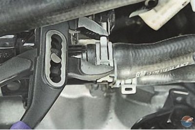
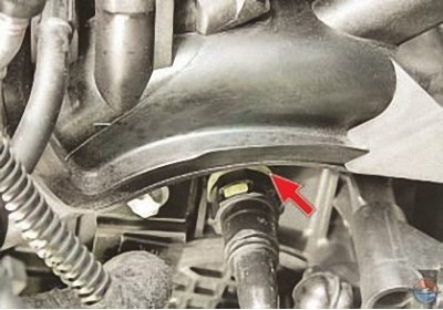
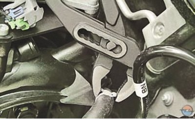
18. Loosen the hose clamp for the coolant outlet hose from the pipe, squeezing its bent antennae with pliers. Slide the clamp over the hose..
19.... and disconnect the hose from the nozzle.
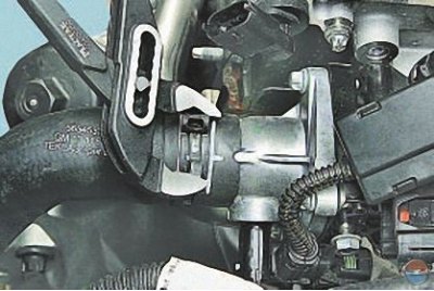
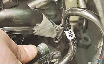
20. Loosen the hose clamp to the thermostat nozzle in the same way..
21.... and disconnect the hose from the nozzle.
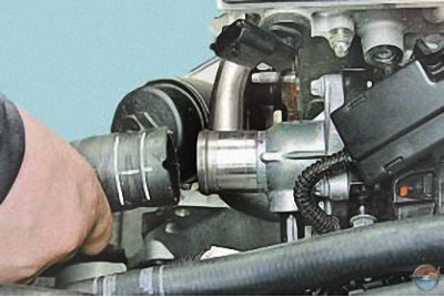
22. Press the latch and disconnect from the inlet pipe (receiver) vacuum hose.
23. Remove the collector (see Removal and installation of the collector, replacement of its gasket).
24. Loosen the hose clamp for the coolant outlet hose from the pipe, squeezing its bent antennae with pliers. Slide the clamp over the hose..
25.... and disconnect the hose.
26. Remove the camshafts (see Removal, troubleshooting and installation of camshafts).
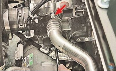
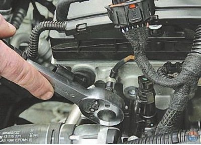
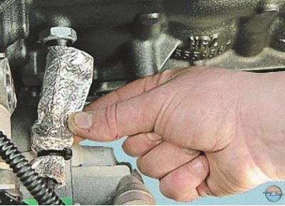
27. Remove the two bolts securing the water distribution pipe to the water pump..
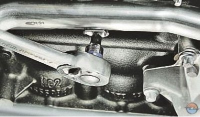
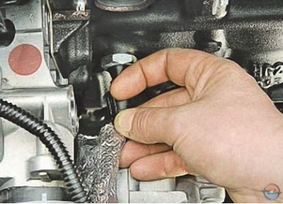
28.... a bolt for fastening the water distribution pipe to the cylinder block..
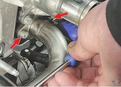
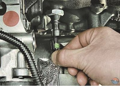
29.... two screws securing the pipe to the thermostat module..
Note. One of the screws securing the pipe to the thermostat module is not visible in the photo, as it is covered by the pipe.
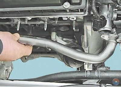
30.... and remove the water distribution pipe.
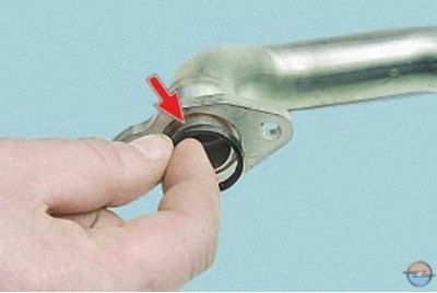
Attention! The flanges of the water distribution pipe are sealed with a rubber ring. Replace the ring each time the joint is disassembled.
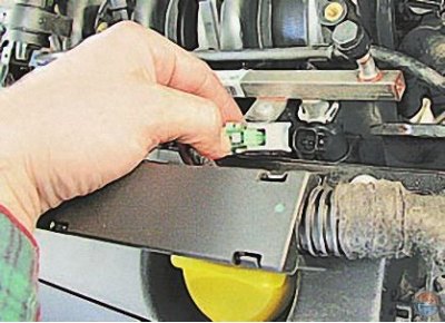
31. Slide the heat shield over the wiring harness..
32.... move the wiring harness retainer to the side..
33.... and disconnect the wiring harness block from the oil pressure sensor.
34. Disconnect the plastic holders of the engine wiring harness from the engine brackets by biting them with pliers, and remove the wiring harness from the engine compartment.
35. Loosen the ten bolts securing the block head to the cylinder block in the sequence shown in fig. 1.
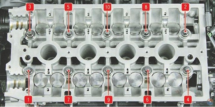
Pic. 1. The procedure for removing the cylinder head bolts
Attention! Bolts of fastening of a head of the block of cylinders can be turned out only on the cold engine.
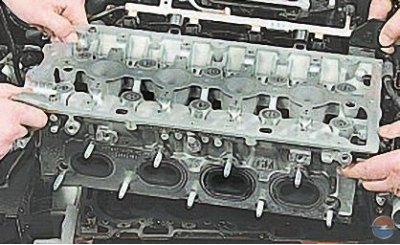
36. Remove the cylinder head assembly with the engine intake pipe..
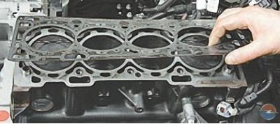
37.... and remove its gasket.
Note. Remove the cylinder head with an assistant, as it is quite heavy.
38. Clean the mating surfaces of the head and block.
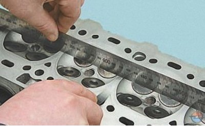
39. Check up a head of the block on lack of a buckling. To do this, placing the ruler with an edge on the surface of the head, first in the middle along, then across and diagonally, measure the gap between the surface of the head and the ruler with a feeler gauge. Grind the cylinder head if the clearance is greater than 0.1mm.
40. Install the cylinder head in the reverse order of removal, taking into account the following:
- remove oil and coolant from the threaded holes of the cylinder head bolts that got there when the head was removed;
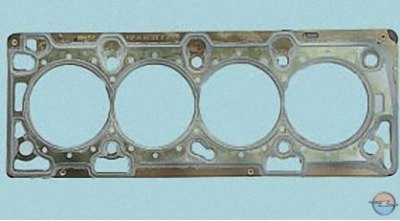
- be sure to install a new head gasket, its reuse is not allowed;
- lubricate the bolts with engine oil;
- tighten the bolts on a cold engine in the order shown in fig. 2, moment.
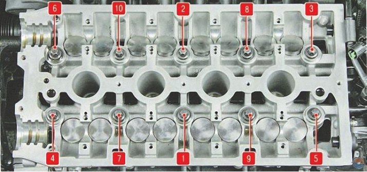
Pic. 2. The procedure for screwing in the cylinder head bolts
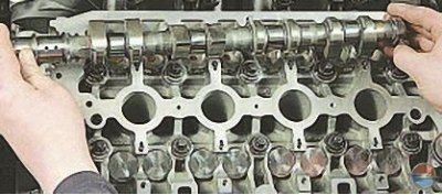
41. Establish camshafts in the sequence specified in subsection Removal, troubleshooting and installation of camshafts.
42. Install all previously removed parts in the reverse order of removal.
Visitor comments