
Note: Before you start dismantling the distributor, find out if replacement parts are available and how much they cost. It may be more cost effective to replace the entire distributor assembly.
Models 14NV
Disassembly
1. After removing the distributor as described in Chapter 18, proceed as follows.
2. Remove the distributor slider and plastic shield.
3. The top support plate can be removed by unscrewing the two mounting screws, however, apart from the vacuum block, no other distributor parts are available and no adjustment is required.
4. If required, the vacuum block can be removed by unscrewing the two screws and detaching the lever from the base plate. Note that the screws are of different lengths, the longer screw also secures one of the breaker-distributor cover brackets.
Inspection
5. The vacuum chamber can be checked by creating a vacuum in the vacuum channel, the driving rod should move inside the block.
After the suction stops, the driving rod must return to its original position.
If the link does not move as described, replace the vacuum chamber.
6. Check the condition of the cover of the breaker-distributor so that there are no signs of corrosion of the contacts, burnt traces in the form of a thin black line between the contacts.
Check that the carbon brush in the center of the cover moves freely. Replace cover if necessary.
7. If the metal part of the slider is severely burnt or weakened, replace it. If there is light soot or corrosion; this can be cleaned with a small file.
8. Check the condition of the O-ring at the rear of the distributor housing, replace if necessary.
Assembly
9. Assembly is carried out in the reverse order. Make sure that the vacuum chamber control arm is properly engaged with the tab on the base plate.
10. Install the distributor as described in Chapter 18, and then check and, if necessary, adjust the ignition timing as described in Chapter 21.
Models 16 SV
Disassembly
11. After removing the distributor as described in Chapter 18, remove the distributor slider and, on a Bosch distributor, remove the plastic shield.
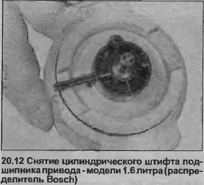
12. With a punch, carefully knock out the roll pin securing the plastic drive bearing to the rear of the distributor shaft (see illustration).
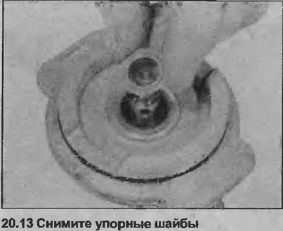
13. Remove drive bearing, remove thrust washers from shaft end (see illustration).
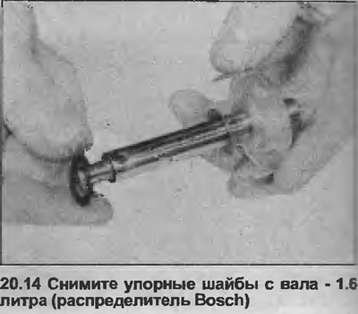
14. Remove the shaft (along with trigger blade) from the distributor housing, remove the thrust washers from the shaft (see illustration).
15. On a Lucas distributor, remove the spring clip from inside the body, then remove the terminal block.
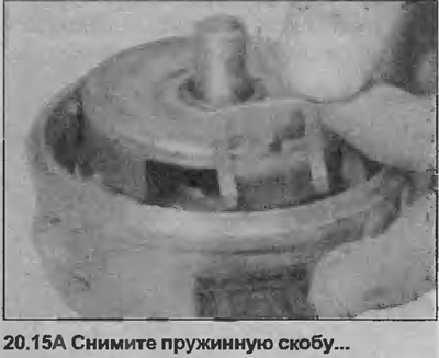
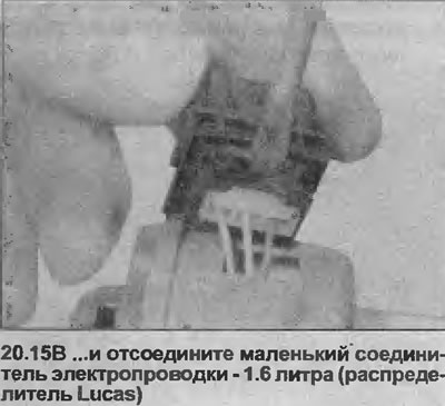
Disconnect the small wiring connector from the inside of the terminal block (see illustrations).
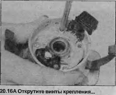
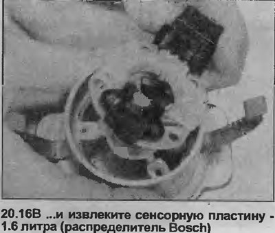
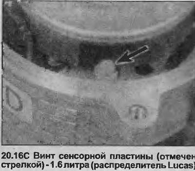
16. Unscrew the screws, remove the sensor plate from the distributor housing (see illustrations).
Inspection
17. Inspect the breaker-distributor cover and distributor runner as described in steps 6 and 7. Inspect the O-rings at the rear of the distributor housing and on the rear of the shaft, replace if necessary.
Assembly
18. Assembly is carried out in the reverse order.
Make sure the thrust washers are correctly positioned.
Note that the drive bearing must be installed so that the drive lug on the bearing fits into the groove on the top of the distributor shaft (it is possible to set the drive bearing 180°from this position).
19. Install the distributor as described in Chapter 18, and then check and, if necessary, adjust the ignition timing as described in Chapter 21.
Models with double overhead camshafts
20. The cover of the breaker-distributor and the distributor slider can be checked as described in points 6 and 7.
Visitor comments