


Contents: Intake manifold pressure sensor ⬇ Oil temperature sensor ⬇ Crankshaft speed/position sensor…⬇
Note: Before you begin, see. Chapter 3. The procedures for removing and installing the ignition system components and the electronic module are given in the corresponding Chapters of this Section.
Intake manifold pressure sensor
Removal
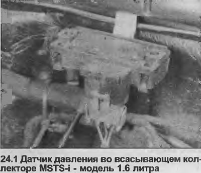
1. The sensor is located on the engine compartment bulkhead, to the left of the MSTS-i module, under the edge of the windshield fairing (see illustration).
2. Disconnect the negative cable from the battery.
3. To access the sensor, lift the edge of the windshield fairing.
4. Disconnect the electrical wiring and vacuum tube from the sensor.
5. Remove the pressure sensor upwards from the bracket.
Installation
6. Install in reverse order. However, Multec models do not have a fuel vapor trap. Therefore, it is necessary to route the sensor vacuum hose so that it runs horizontally from the sensor to the throttle body. This will prevent fuel drips from entering the sensor or hose.
Oil temperature sensor
Removal
7. The sensor is screwed into the cylinder block from the intake manifold side, next to the starter.
8. The sensor is easily accessible from above.
9 Disconnect the negative cable from the battery.
10. Disconnect the sensor wiring.
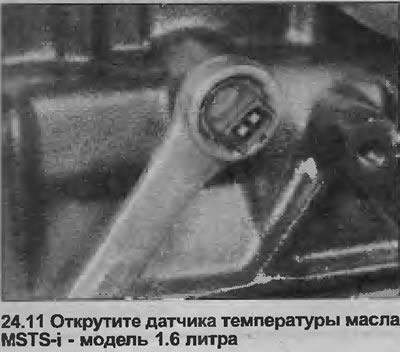
11. Use a wrench to unscrew the sensor (see illustration). Plug the hole in the cylinder block to prevent dirt from entering and further oil loss.
Installation
12. Perform installation in reverse order.
Crankshaft speed/position sensor (1.8 liter models)
Removal
13. The sensor is located at the bottom of the cylinder block behind the oil pump, on the exhaust manifold side.
14. Disconnect the negative cable from the battery.
15. Release the retaining clips of the outer toothed drive belt cover, unfasten the sensor wiring from the cover.
(Original posted on the website: «www.OPELBOOK.ru»)
16. Disconnect the electrical wiring from the sensor, noting its location.
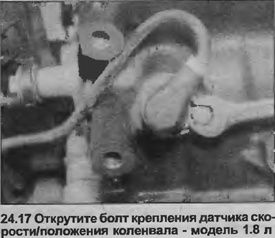
17. Unscrew the mounting bolt, remove the sensor from the cylinder block (see illustration).
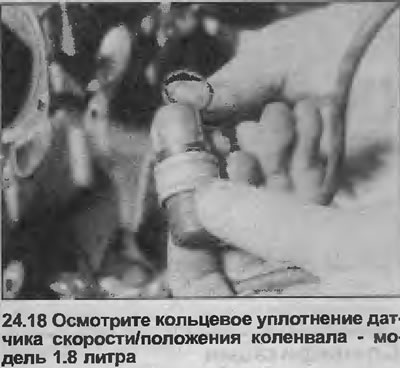
18. Check the condition of the sensor O-ring, replace if necessary (see illustration).
Installation
19. Install in reverse order. Correctly position the sensor wiring on the toothed drive belt cover.
Visitor comments