
OpelBook.ru
Cars AvtoVAZ Cars Mitsubishi Cars BMW Cars Mercedes Cars Nissan Cars Toyota Cars Chevrolet
English Русский
Български
Беларускі
Український
Српски
Hrvatski
Română
Polski
Slovenský
Magyar
 |  Sitemap  |  Contacts  |    


Main Astra Corsa Insignia Kadett Omega Vectra Zafira Others Articles
Frontera A (1991-1998, petrol) Frontera B (1998-2004) Ascona C (1981-1988) Vivaro A (2001-2014)
  • Main
  • Opel
  • Ascona C
  • Power unit
  • Contact ignition system
  • Distributor — disassembly, inspection and assembly

Distributor — disassembly, inspection and assembly (Opel Ascona C)

            0

1. Before disassembling the distributor, check whether spare parts are available for sale. In some cases (in case of severe wear of the distributor) it may be more profitable to replace it as a whole.

2. Disassembly of the distributor should be carried out on a clean work table, where the removed parts can be laid out in order.

3. Remove the waterproof cover and the distributor cap together with the wires (if it hasn't been done yet) (see section 3). Remove the runner and plastic plate.

4. Remove the breaker (see section 4).

5. Remove the capacitor (see section 5).

6. Remove the retaining ring securing the vacuum regulator control rod to the plate shaft (see photo).
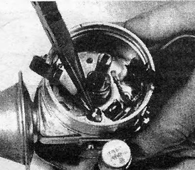
Photo 7.6. Removing the vacuum regulator rod retaining ring.

Photo 7.6. Removing the vacuum regulator rod retaining ring.


7. Loosen the screws securing the vacuum regulator and remove it, disconnecting the control rod (see photos).
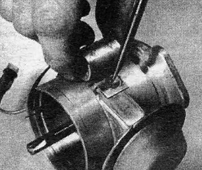
Photo 7.7A. Screw securing condenser and vacuum regulator.
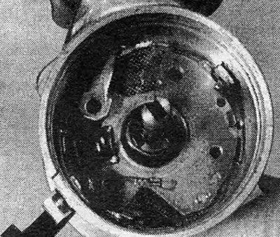
Photo 7.7A. Screw securing condenser and vacuum regulator.


Photo 7.7B. Disconnecting the vacuum regulator control rod.

Photo 7.7B. Disconnecting the vacuum regulator control rod.


8. Loosen the screws and remove the support plate (see photos).
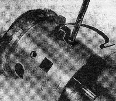
Photo 7.8A. Removing the screw securing the support plate and clamp.
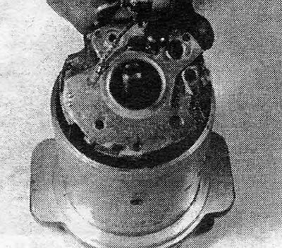
Photo 7.8A. Removing the screw securing the support plate and clamp.


Photo 7.8B. Removing the support plate.

Photo 7.8B. Removing the support plate.


9. Inspect and, if necessary, remove the centrifugal governor weights and springs, noting their relative positions (see photos).
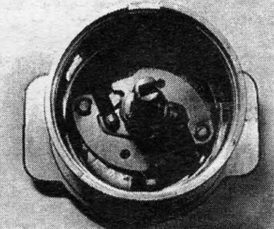


Photo 7.9. Weights and springs of the centrifugal governor.

Photo 7.9. Weights and springs of the centrifugal governor.


Material copied from the portal opelbook

10. To remove the roller, you must first remove the drive leash. Using a small punch, drive the pin out and pull the roller out through the top.

11. Clean all parts with a grease solvent and wipe them dry or dry with compressed air.

12. Inspect all parts for obvious wear and damage. Check the play of the shaft and inspect the teeth of the drive gear or the surfaces of the pawl for wear. Replace damaged or questionable parts.

13. Before assembling the distributor, lubricate all moving parts and centrifugal weight springs with grease.

14. Install the shaft and drive gear or pawl in place. Secure the gear (dog) with a new pin.

15. Assemble the centrifugal regulator, ensuring that the weights and springs are installed correctly.

16. Install the contact breaker plates and tighten the screws that secure them.

17. Install the vacuum regulator in place and tighten the screws that secure it. Connect the control rod to the shaft and secure it with a retaining ring. Apply a small amount of grease to the roller.


18. Install the capacitor (see section 5).

19. Install the contact breaker (see section 4) and adjust the contact gap (see section 3).

20. Lubricate the moving parts of the breaker support plate with clean engine oil and apply a small amount of high-temperature grease to the cam surface.

21. Check the roller for free rotation and the breaker contacts for correct operation. Use your finger to turn the runner in the direction opposite to its normal direction of rotation: it should return back to its original static position.

22. The distributor is ready for installation on the engine.


This article is available at russian, bulgarian, belarusian, ukrainian, serbian, croatian, romanian, polish, slovak, hungarian
Checking the article: Kornev Georgy

Share information:

Previous articles
Opel Ascona C: Contact ignition system
Next articles

Distributor — removal and installation
Capacitor — removal, inspection and installation
Breaker contacts — removal and installation
Breaker contacts — adjustment of the gap and angle of the closed state of the contacts
Ignition System — Routine Maintenance
Ignition system with mechanical contact breaker — general description
Ignition timing angle — adjustment
Spark plugs and high tension wires — common part
Ignition coil — common part
TDC position sensor
Ignition Switch — Removal and Installation
Ignition system with mechanical contact breaker — troubleshooting


See similar ones from other Opel car manuals:
▶ Distributor belt — removal, installation and adjustment Opel Astra F (1991-1998, petrol)
▶ Removal and installation the ignition distributor (engine… Opel Corsa B (1993-2000)
▶ Removal and installation the ignition system distributor Opel Kadett E (1984-1995)
▶ Breaker distributor cover and distributor runner — removal… Opel Omega A (1986-1993)
▶ Breaker distributor cover and high voltage wires check Opel Vectra A (1988-1995, petrol)
Link to this page in different formats

Visitor comments


No comments yet


How much will 48 + 26 =


Vivaro A (2001-2014) 
  • General information
  • User manual
  • Power unit
  • Petrol engine F4R
  • Diesel engine F9Q
  • Diesel engine G9U
  • Transmission
  • Clutch and drive shafts
  • Manual gearbox
  • Chassis
  • Front suspension
  • Rear suspension
  • Brake system
  • Body
  • Exterior
  • Interior
  • Electrical equipment
  • Heating and ventilation
  • Air conditioner
  • Equipment and devices
  • Electrical diagrams
Ascona C (1981-1988) 
  • General information
  • Maintenance
  • Power unit
  • Gasoline engines
  • Diesel engines
  • Cooling system
  • Fuel and exhaust system
  • Contact ignition system
  • Contactless ignition system
  • Transmission
  • Clutch
  • Mechanical gearbox
  • Automatic gearbox
  • Drive shafts
  • Chassis
  • Steering
  • Brake system
  • Car suspension
  • Body
  • Exterior
  • Interior
  • Doors and windows
  • Electrical equipment
  • Equipment and devices
  • Power devices
  • Electrical circuits
Frontera B (1998-2004) 
  • General information
  • User manual
  • Maintenance
  • Power unit
  • Petrol engines 2.2 l
  • Petrol engines 3.2 l
  • Diesel engines 2.2 l
  • Cooling system
  • Fuel system (petrol)
  • Fuel system (diesel)
  • Ignition system
  • Transmission
  • Clutch
  • Manual gearbox MUA5C
  • Automatic gearbox 4L30E
  • Chassis
  • Suspension and axles
  • Steering
  • Brake system
  • Body
  • Exterior
  • Interior
  • Doors, locks and windows
  • Heating and air conditioning
  • Electrical equipment
  • Power devices
  • Equipment and devices
  • Lighting and signaling
  • Electrical diagrams
Frontera A (1991-1998, petrol) 
  • General information
  • Introduction to guide
  • User manual
  • Maintenance
  • Power unit
  • Engine repair
  • Lubrication system
  • Cooling system
  • Power and exhaust system
  • Engine electrics
  • Transmission
  • Clutch
  • Mechanical gearbox
  • Cardan shafts
  • Chassis
  • Brake system
  • Front suspension
  • Rear suspension
  • Steering
  • Body
  • Repair and care
  • Electrical equipment
  • Equipment and devices
  • Electrical circuits
OpelBook.ru © 2017–2026 · Mobile version · · Sitemap: EN BG BY UA RS HR RO PL SK HU · Feedback · Site search
Astra F, petrol · Astra G, petrol · Astra G · Astra H · Astra J, petrol · Corsa B · Corsa C, petrol · Corsa C · Insignia A · Kadett D · Kadett E · Omega A · Omega B · Omega B2 · Vectra A, petrol · Vectra A · Vectra B, petrol · Vectra B · Vectra C · Zafira A, petrol · Frontera A, petrol · Frontera B · Ascona C · Vivaro A ·
We want your visit to be comfortable 🤝! We use cookies 🍪 to make that happen.