
OpelBook.ru
Cars AvtoVAZ Cars Mitsubishi Cars BMW Cars Mercedes Cars Nissan Cars Toyota Cars Chevrolet
English Русский
Български
Беларускі
Український
Српски
Hrvatski
Română
Polski
Slovenský
Magyar
 |  Sitemap  |  Contacts  |    


Main Astra Corsa Insignia Kadett Omega Vectra Zafira Others Articles
Frontera A (1991-1998, petrol) Frontera B (1998-2004) Ascona C (1981-1988) Vivaro A (2001-2014)
  • Main
  • Opel
  • Ascona C
  • Power unit
  • Contact ignition system
  • Ignition system with mechanical contact breaker — general description

Ignition system with mechanical contact breaker — general description (Opel Ascona C)

            0

In order for the engine to operate properly, it is necessary for the spark plug to ignite the working mixture in the combustion chamber at the right time in relation to the engine speed and its load. Low voltage from the battery is supplied to the ignition coil, where it is converted into high voltage, the value of which is sufficient to cause a spark to jump between the spark plug electrodes at high pressure developed in the cylinders.

The ignition system is divided into 2 circuits: high and low voltage.

Low voltage circuit (sometimes also called primary) consists of a battery, a wire leading to the ignition switch, a wire leading from the ignition switch to the primary winding of the coil, and a wire leading from the primary winding of the coil to the contacts of the breaker and the capacitor in the distributor.

The high voltage circuit consists of the secondary winding of the coil, the spark plug wire leading from the center of the coil to the center of the distributor cap, the rotor, the spark plug wires leading to the spark plugs, and the spark plugs themselves.

The ignition system works as follows. Low voltage is converted into high voltage in the ignition coil by opening and closing the contacts of the breaker in the low voltage circuit. High voltage is supplied through the "carbon" in the center of the distributor cap to the rotor on the cap, and whenever the rotor is brought into contact with one of the four electrodes on the distributor cap that are connected to the spark plug wires, the opening and closing of the breaker contacts causes a build-up of high voltage, causing a spark to jump between the rotor and the corresponding electrode. The voltage is transmitted via the ignition wire to the spark plug, between the electrodes of which a spark jumps, causing the mixture to ignite, after which the current goes to ground.


To ensure that the mixture is ignited at the right time in relation to the engine speed and load, the ignition timing is automatically adjusted.

The ignition timing angle is controlled by mechanical and vacuum regulators. Mechanical (centrifugal) the regulator consists of two weights, which, due to centrifugal force, diverge when the speed of rotation of the distributor shaft increases and turn the cam relative to the distributor shaft, thereby accelerating the spark jump. The weights are held by two springs, and the correct mechanical adjustment of the ignition timing angle depends on the tension of the springs.

The vacuum regulator consists of a membrane, one side of which is connected by a thin tube to the carburetor, and the other to the contact breaker plate. The vacuum in the intake manifold and carburetor, which varies depending on engine speed and throttle opening, causes the diaphragm to move, which moves the contact breaker plate accordingly, accelerating or retarding the spark jump (see photo).
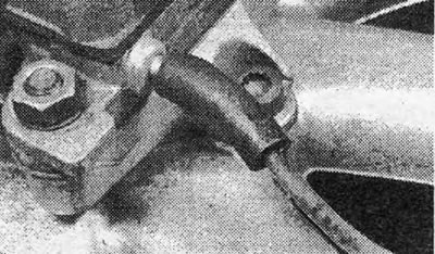
Photo 1.8. Connecting the distributor vacuum tube to the carburetor.

Photo 1.8. Connecting the distributor vacuum tube to the carburetor.


A resistor in the low voltage wire to the coil holds the coil voltage at 6 volts during normal operation. This resistor is bypassed when the starter is engaged to compensate for the resulting drop in battery voltage.


This article is available at russian, bulgarian, belarusian, ukrainian, serbian, croatian, romanian, polish, slovak, hungarian
Checking the article: Kornev Georgy

Share information:

Previous articles
Opel Ascona C: Contact ignition system
Next articles

Ignition system — specification
Ignition System — Routine Maintenance
Breaker contacts — adjustment of the gap and angle of the closed state of the contacts
Breaker contacts — removal and installation
Capacitor — removal, inspection and installation
Distributor — removal and installation
Distributor — disassembly, inspection and assembly


See similar ones from other Opel car manuals:
▶ Ignition system — general information Opel Astra G (1998-2004, petrol)
▶ Ignition system — general information Opel Kadett D (1979-1984)
▶ Ignition system — general description Opel Omega B2 (1999-2003)
▶ Ignition system — general description Opel Vectra A (1988-1995, petrol)
▶ General information about the fuel injection system of a… Opel Corsa B (1993-2000)
Link to this page in different formats

Visitor comments


No comments yet


How much will 48 + 25 =


Vivaro A (2001-2014) 
  • General information
  • User manual
  • Power unit
  • Petrol engine F4R
  • Diesel engine F9Q
  • Diesel engine G9U
  • Transmission
  • Clutch and drive shafts
  • Manual gearbox
  • Chassis
  • Front suspension
  • Rear suspension
  • Brake system
  • Body
  • Exterior
  • Interior
  • Electrical equipment
  • Heating and ventilation
  • Air conditioner
  • Equipment and devices
  • Electrical diagrams
Ascona C (1981-1988) 
  • General information
  • Maintenance
  • Power unit
  • Gasoline engines
  • Diesel engines
  • Cooling system
  • Fuel and exhaust system
  • Contact ignition system
  • Contactless ignition system
  • Transmission
  • Clutch
  • Mechanical gearbox
  • Automatic gearbox
  • Drive shafts
  • Chassis
  • Steering
  • Brake system
  • Car suspension
  • Body
  • Exterior
  • Interior
  • Doors and windows
  • Electrical equipment
  • Equipment and devices
  • Power devices
  • Electrical circuits
Frontera B (1998-2004) 
  • General information
  • User manual
  • Maintenance
  • Power unit
  • Petrol engines 2.2 l
  • Petrol engines 3.2 l
  • Diesel engines 2.2 l
  • Cooling system
  • Fuel system (petrol)
  • Fuel system (diesel)
  • Ignition system
  • Transmission
  • Clutch
  • Manual gearbox MUA5C
  • Automatic gearbox 4L30E
  • Chassis
  • Suspension and axles
  • Steering
  • Brake system
  • Body
  • Exterior
  • Interior
  • Doors, locks and windows
  • Heating and air conditioning
  • Electrical equipment
  • Power devices
  • Equipment and devices
  • Lighting and signaling
  • Electrical diagrams
Frontera A (1991-1998, petrol) 
  • General information
  • Introduction to guide
  • User manual
  • Maintenance
  • Power unit
  • Engine repair
  • Lubrication system
  • Cooling system
  • Power and exhaust system
  • Engine electrics
  • Transmission
  • Clutch
  • Mechanical gearbox
  • Cardan shafts
  • Chassis
  • Brake system
  • Front suspension
  • Rear suspension
  • Steering
  • Body
  • Repair and care
  • Electrical equipment
  • Equipment and devices
  • Electrical circuits
OpelBook.ru © 2017–2026 · Mobile version · · Sitemap: EN BG BY UA RS HR RO PL SK HU · Feedback · Site search
Astra F, petrol · Astra G, petrol · Astra G · Astra H · Astra J, petrol · Corsa B · Corsa C, petrol · Corsa C · Insignia A · Kadett D · Kadett E · Omega A · Omega B · Omega B2 · Vectra A, petrol · Vectra A · Vectra B, petrol · Vectra B · Vectra C · Zafira A, petrol · Frontera A, petrol · Frontera B · Ascona C · Vivaro A ·
We want your visit to be comfortable 🤝! We use cookies 🍪 to make that happen.