


Removal
1. Place the vehicle on a two-post lift.
2. Disconnect the battery, starting with the negative cable.
3. Remove the engine guard, disconnect the wiring connector from the air flow meter, remove the air filter, disconnect the pipe from the charge air cooling radiator, remove the engine cover, remove the right wheel, right headlight.
4. Install the Mot. 1367-02 support for the engine (figure 4.18).
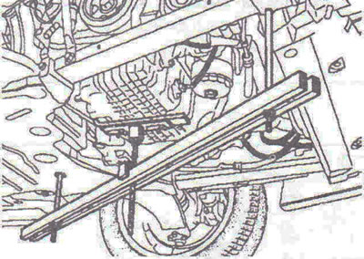
Figure 4.18. Install the Mot. 1367-02 engine support.
5. Disconnect the engine suspension rod.
6. Disconnect the power steering fluid reservoir and pipes from the right support bracket.
7. Remove the right support bracket and suspension travel limiter.
8. Remove the upper timing belt cover and lifting eye (figure 4.19).
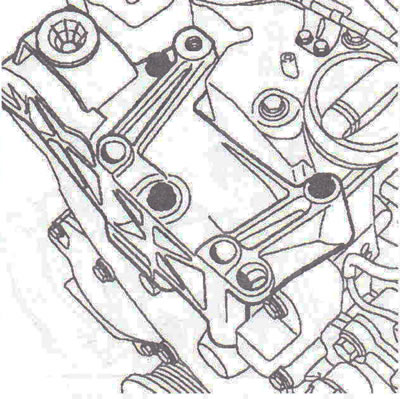
Figure 4.19. Remove the upper timing belt cover and lifting eye.
9. Remove the middle timing belt cover (figure 4.20).
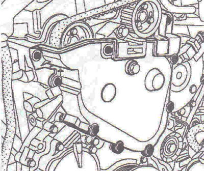
Figure 4.20. Remove the middle timing belt cover.
10. Unscrew cover 1 from the hole for the TDC locking device (figure 4.21).
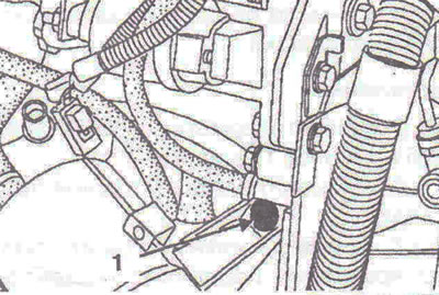
Figure 4.21. Unscrew cover 1 from the hole for the TDC lock.
Setting the valve timing
11. Install the 2 TDC mark on the crankshaft pulley vertically (figure 4.22).
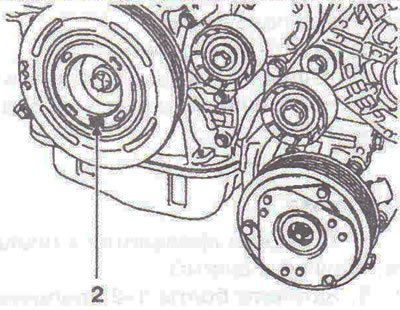
Figure 4.22. Setting the 2 TDC mark on the crankshaft pulley vertically.
12. Install TDC locking tool Mot. 1536.
13. Rotate the crankshaft clockwise while pressing the TDC lock until it reaches the setting point.
14. The grooves on the camshafts must be positioned vertically (figure 4.23).
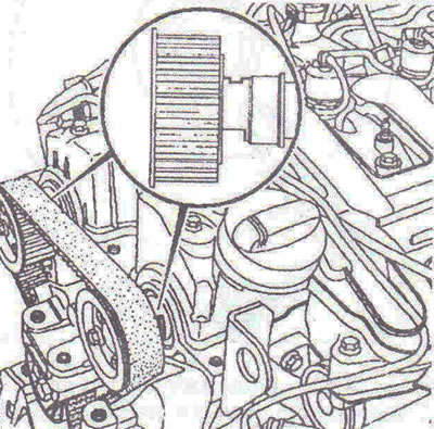
Figure 4.23. The grooves on the camshafts must be positioned vertically.
15. The inlet and outlet camshafts can be adjusted using tools Mot. 1534 and Mot. 1537 (figure 4.24a, b).
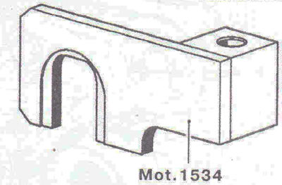
Figure 4.24a. Mot. 1534 tool for adjusting the intake camshaft.
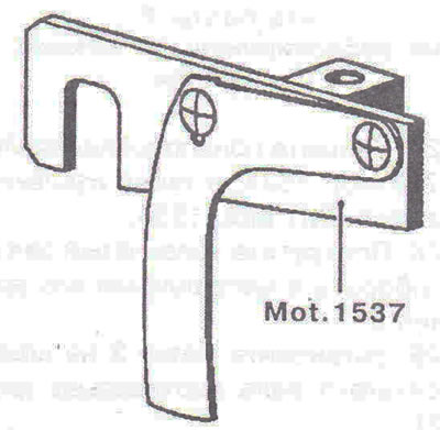
Figure 4.24b. Mot. 1537 device for adjusting the exhaust camshaft.
16. Install tools Mot. 1534 and Mot. 1537 in the order shown below.
For intake camshaft
17. Install tool Mot. 1534, screwing in the bolt with 1 hand (figure 4.25). Loosen the three camshaft pulley mounting bolts 2 by one turn. Turn the intake camshaft clockwise using bolt 3 (using a 13mm wrench) so that the finger of the Mot. 1534 device is positioned on the cylinder head. Lock bolt 1 of the Mot. 1534 tool.
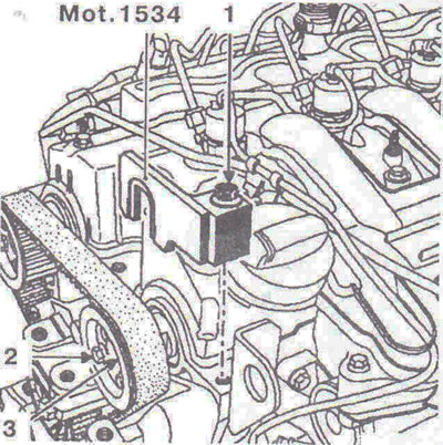
Figure 4.25. Install tool Mot. 1534.
For exhaust camshaft
18. Install tool Mot. 1537, screwing in bolt 4 by hand, drawing 4.26). Loosen the three bolts 5 securing the camshaft pulley by one turn. Turn the intake camshaft clockwise using bolt 6 (using a 16mm wrench) so that the finger of the Mot. 1537 device is positioned on the cylinder head. Lock bolt 4 of the Mot. 1537 tool.
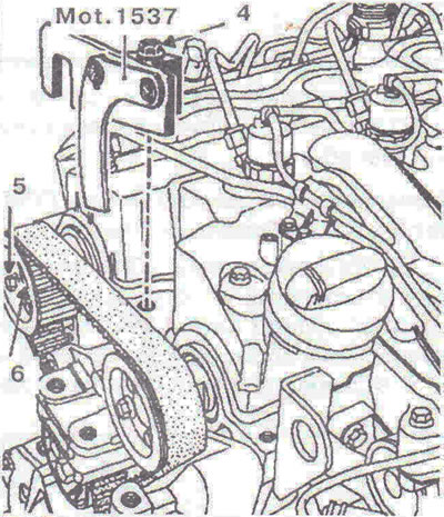
Figure 4.26. Install tool Mot. 1537.
19. Loosen the timing belt by unscrewing bolt 1 of the tension roller fastening (figure 4.27). Unscrew three bolts 2, then remove the exhaust camshaft pulley, remove the timing belt, tension roller, idler roller.
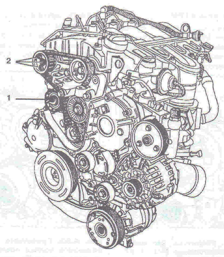
Figure 4.27. Loosen the timing belt by unscrewing bolt 1 securing the tension roller.
Installation
Adjusting the valve timing
20. Set mark 2 on the crankshaft pulley vertically (figure 4.22).
21. Loosen the intake camshaft pulley mounting bolts by one turn.
Attention! When replacing the timing belt, it is recommended to replace the tensioner and idler rollers.
22. Install the timing belt, starting with the idler pulley 1, then install it on the idler pulley 2, on the intake camshaft pulley and on the tensioner pulley 3 (figure 4.28). Install the exhaust camshaft pulley by screwing in its mounting bolts. It is recommended to replace the bolts first. Install the timing belt onto the exhaust camshaft pulley.
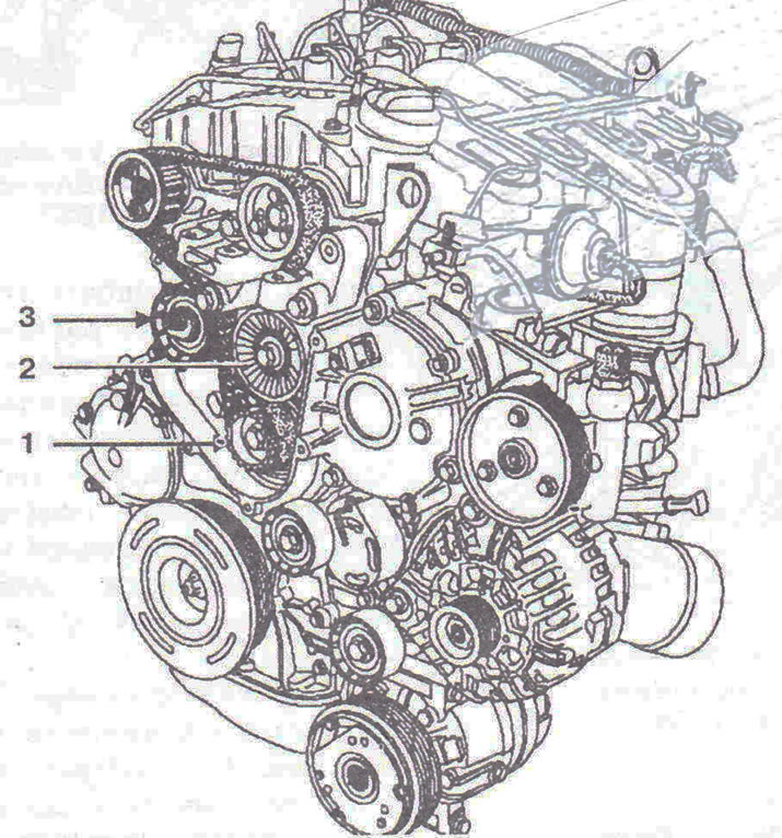
Figure 4.28. Install the timing belt, starting with the idler pulley 1, then install it on the idler pulley 2, on the intake camshaft pulley and on the tensioner pulley 3.
Timing Belt Tension
23. Make sure that eye 1 on tool Mot. 1537 can move freely along the vertical axis (figure 4.29). Insert a 6 mm wrench into hole 2 of the tension roller eccentric.
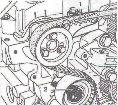
Figure 4.29. Check that eye 1 on tool Mot. 1537 can move freely along the vertical axis. Insert a 6 mm wrench into hole 2 of the tension roller eccentric.
24. Turn the tension roller eccentric counterclockwise until surface 3 of eye 1 aligns with the upper surface 4 of tool Mot. 1537 (figure 4.30).
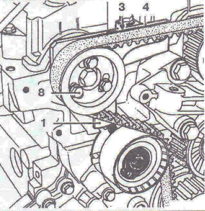
Figure 4.30. Turn the tension roller eccentric counterclockwise until surface 3 of eye 1 aligns with the upper surface 4 of tool Mot. 1537.
25. The movable pointer 5 of the tension roller must be in line with the groove 6 (figure 4.31).
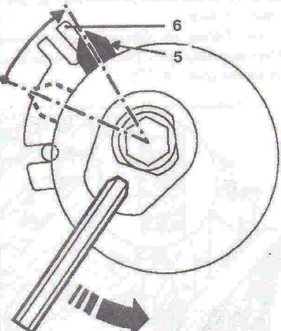
Figure 4.31. The movable pointer 5 of the tension roller must be in line with the groove 6.
26. Make sure that bolts 8 are not locked in the lower position (figure 4.32). Tightening torques: bolt 7 for fastening the tension roller - 25 Nm, bolts 8 for fastening the camshaft pulleys - 10 Nm.
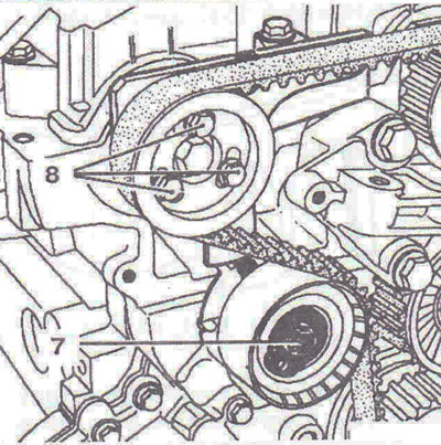
Figure 4.32. Make sure that bolts 8 are not locked in the lower position.
27. Remove tools Mot. 1537 and Mot. 1534 and extract TDC locking tool Mot. 1536.
28. Rotate the crankshaft two revolutions in the direction of its rotation.
29. Set mark 2 on the crankshaft pulley vertically (figure 4.22).
For intake camshaft
30. Install tool Mot. 1534, screwing in the bolt with 1 hand (figure 4.25). Loosen the three camshaft pulley mounting bolts 2 by one turn. Turn the intake camshaft clockwise using bolt 3 (using a 13mm wrench) so that the finger of the Mot. 1534 device is positioned on the cylinder head. Lock bolt 1 of the Mot. 1534 tool.
For exhaust camshaft
31. Install tool Mot. 1537, screwing in bolt 4 by hand (figure 4.26). Loosen the three bolts 5 securing the camshaft pulley by one turn. Turn the intake camshaft clockwise using bolt 6 (using a 16mm wrench) so that the finger of the Mot. 1537 device is positioned on the cylinder head. Lock bolt 4 of the Mot. 1537 tool.
Checking the valve timing and timing belt tension
32. Unscrew the bolt 7 of the tension roller, holding the cam with a 6 mm wrench (figure 4.33). Turn the tension roller eccentric clockwise until surface 9 of eye 1 is aligned with the upper surface 4 of tool Mot. 1537.
33. The movable pointer 5 of the tension roller must be located in the middle of the groove 10 (figure 4.34).
34. Tighten bolt 7 of the tension roller - 25 Nm, bolts 8 of the camshaft pulleys - 10 Nm.
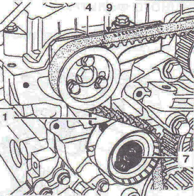
Figure 4.33. Unscrew bolt 7 of the tension roller, holding the cam with a wrench. Turn the tension roller eccentric clockwise until surface 9 of eye 1 is aligned with the upper surface 4 of tool Mot. 1537.
35. Remove tools Mot. 1537 and Mot. 1534 and extract TDC locking tool Mot. 1536.
36. Screw in the TDC locking hole cover (figure 4.35). The tightening torque of the cover is 30 Nm.
37. Install the middle timing belt cover. The tightening torque of the middle timing belt cover mounting bolts is 10 Nm.
38. Install the upper timing belt cover. The tightening torque of the upper timing belt cover mounting bolts is 25 Nm.
39. Further installation is carried out in the reverse order of removal.
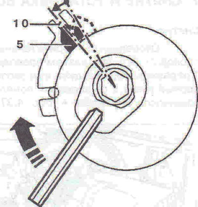
Figure 4.34. The movable indicator 5 of the tension roller must be located in the middle of the groove 10.
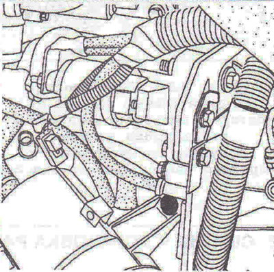
Figure 4.35. Screw in the TDC locking hole cover.
Visitor comments