
OpelBook.ru
Cars AvtoVAZ Cars Mitsubishi Cars BMW Cars Mercedes Cars Nissan Cars Toyota Cars Chevrolet
English Русский
Български
Беларускі
Український
Српски
Hrvatski
Română
Polski
Slovenský
Magyar
 |  Sitemap  |  Contacts  |    


Main Astra Corsa Insignia Kadett Omega Vectra Zafira Others Articles
Frontera A (1991-1998, petrol) Frontera B (1998-2004) Ascona C (1981-1988) Vivaro A (2001-2014)
  • Main
  • Opel
  • Vivaro A
  • Power unit
  • Diesel engine G9U
  • Removal and installation the intake manifold

Removal and installation the intake manifold (Opel Vivaro A)

            0

Contents: 9.1. Upper part of the intake…⬇ Installation ⬇ 9.2. Lower part of the intake…⬇

9.1. Upper part of the intake manifold


Removal


1. Disconnect the battery, starting with the negative cable.

2. Remove the injectors, high pressure accumulator, high pressure accumulator protection.

3. Disconnect the wiring connectors from the glow plugs.

4. Unhook the harness guard 1 (figure 4.46).
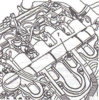
Figure 4.46. Unhook the wire harness guard 1.

Figure 4.46. Unhook the wire harness guard 1.


5. Move the wire harness to the side.

6. Remove the exhaust gas recirculation pipe 2 with seals, bracket 3 between the air distributor and the power steering pump (figure 4.47). Loosen clamp 4 of the damper/intake manifold connecting pipe.
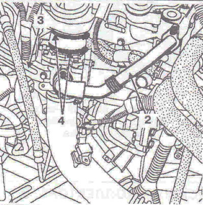
Figure 4.47. Remove exhaust gas recirculation pipe 2 with seals, bracket 3 between the air…

Figure 4.47. Remove exhaust gas recirculation pipe 2 with seals, bracket 3 between the air distributor and the power steering pump.


7. Install the engine lifting tool Mot. 1367.

8. Remove the support, unscrew the bolts securing the upper part of the intake manifold and remove the upper part of the manifold (figure 4.48).
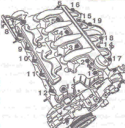
Figure 4.48. The order of unscrewing the bolts securing the upper part of the intake manifold.

Figure 4.48. The order of unscrewing the bolts securing the upper part of the intake manifold.


Installation


9. Replace the upper intake manifold gaskets with new ones (figure 4.49).
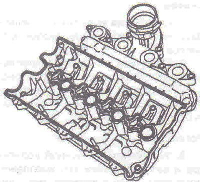
Figure 4.49. Replace the upper intake manifold gaskets with new ones.

Figure 4.49. Replace the upper intake manifold gaskets with new ones.


The source is on the online website (OpelBook.ru)

10. Apply Rhodorseal 5661 to the camshaft bearing cap mounting surfaces (figure 4.50a, b).
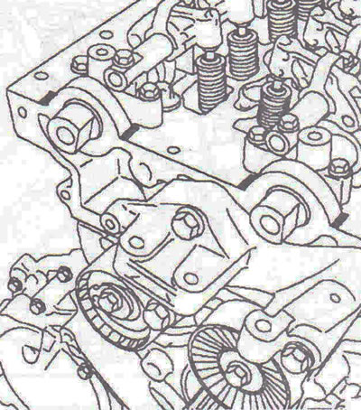
Figure 4.50a. Timing belt side.
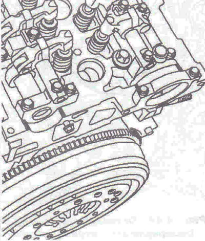
Figure 4.50a. Timing belt side.


Figure 4.50b. Flywheel side.

Figure 4.50b. Flywheel side.


11. Install the rocker arm cover/intake manifold. Tighten the upper intake manifold mounting bolts to 12 Nm in the order shown in Figure 4.51.
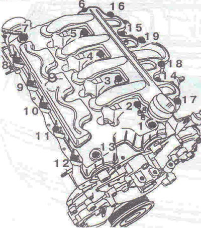
Figure 4.51. Tightening order of the bolts securing the upper part of the intake manifold.

Figure 4.51. Tightening order of the bolts securing the upper part of the intake manifold.


12. Further installation is carried out in the reverse order of removal.

9.2. Lower part of the intake manifold


Removal


1. Remove the upper intake manifold and air distributor.

2. Unscrew the bolts securing the lower part of the intake manifold and remove it (figure 4.52).
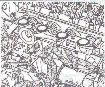
Figure 4.52. Unscrew the bolts securing the lower part of the intake manifold and remove it.

Figure 4.52. Unscrew the bolts securing the lower part of the intake manifold and remove it.


Installation


3. Replace the lower intake manifold gaskets with new ones.

4. Install the lower intake manifold and install the bolts, but do not tighten them.

5. Tighten the lower intake manifold mounting bolts to 12 Nm (figure 4.53).
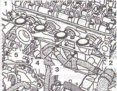
Figure 4.53. Tighten the lower intake manifold mounting bolts.

Figure 4.53. Tighten the lower intake manifold mounting bolts.


This article is available at russian, bulgarian, belarusian, ukrainian, serbian, croatian, romanian, polish, slovak, hungarian
Checking the article: Meshcheryakov Damir

Share information:

Previous articles
Opel Vivaro A: Diesel engine G9U
Next articles

Removal and installation the air distributor
Removal and installation the air filter
Removal and installation the timing belt
Removal and installation the accessory drive belt
Removal and installation the oil pump
Removal and installation the pallet
Removal and installation the exhaust manifold
Pressure regulation
Removal and installation a turbocharger
Fuel injection system
Technical characteristics of fuel injection system components
Removal and installation the high pressure fuel pump


See similar ones from other Opel car manuals:
▶ Intake manifold — removal and installation Opel Astra F (1991-1998, petrol)
▶ Removal and installation the intake manifold — 1.6 and 1.8… Opel Insignia A (2008-2017)
▶ Intake Manifold Heater Element (Carburetor Models) —… Opel Omega A (1986-1993)
▶ Intake manifold — removal and installation Opel Vectra A (1988-1995, petrol)
▶ Intake manifold and pipeline of 1.4 and 1.6 DOHC engines —… Opel Zafira A (1999-2005, petrol)
Link to this page in different formats

Visitor comments


No comments yet


How much will 35 + 11 =


Vivaro A (2001-2014) 
  • General information
  • User manual
  • Power unit
  • Petrol engine F4R
  • Diesel engine F9Q
  • Diesel engine G9U
  • Transmission
  • Clutch and drive shafts
  • Manual gearbox
  • Chassis
  • Front suspension
  • Rear suspension
  • Brake system
  • Body
  • Exterior
  • Interior
  • Electrical equipment
  • Heating and ventilation
  • Air conditioner
  • Equipment and devices
  • Electrical diagrams
Ascona C (1981-1988) 
  • General information
  • Maintenance
  • Power unit
  • Gasoline engines
  • Diesel engines
  • Cooling system
  • Fuel and exhaust system
  • Contact ignition system
  • Contactless ignition system
  • Transmission
  • Clutch
  • Mechanical gearbox
  • Automatic gearbox
  • Drive shafts
  • Chassis
  • Steering
  • Brake system
  • Car suspension
  • Body
  • Exterior
  • Interior
  • Doors and windows
  • Electrical equipment
  • Equipment and devices
  • Power devices
  • Electrical circuits
Frontera B (1998-2004) 
  • General information
  • User manual
  • Maintenance
  • Power unit
  • Petrol engines 2.2 l
  • Petrol engines 3.2 l
  • Diesel engines 2.2 l
  • Cooling system
  • Fuel system (petrol)
  • Fuel system (diesel)
  • Ignition system
  • Transmission
  • Clutch
  • Manual gearbox MUA5C
  • Automatic gearbox 4L30E
  • Chassis
  • Suspension and axles
  • Steering
  • Brake system
  • Body
  • Exterior
  • Interior
  • Doors, locks and windows
  • Heating and air conditioning
  • Electrical equipment
  • Power devices
  • Equipment and devices
  • Lighting and signaling
  • Electrical diagrams
Frontera A (1991-1998, petrol) 
  • General information
  • Introduction to guide
  • User manual
  • Maintenance
  • Power unit
  • Engine repair
  • Lubrication system
  • Cooling system
  • Power and exhaust system
  • Engine electrics
  • Transmission
  • Clutch
  • Mechanical gearbox
  • Cardan shafts
  • Chassis
  • Brake system
  • Front suspension
  • Rear suspension
  • Steering
  • Body
  • Repair and care
  • Electrical equipment
  • Equipment and devices
  • Electrical circuits
OpelBook.ru © 2017–2026 · Mobile version · · Sitemap: EN BG BY UA RS HR RO PL SK HU · Feedback · Site search
Astra F, petrol · Astra G, petrol · Astra G · Astra H · Astra J, petrol · Corsa B · Corsa C, petrol · Corsa C · Insignia A · Kadett D · Kadett E · Omega A · Omega B · Omega B2 · Vectra A, petrol · Vectra A · Vectra B, petrol · Vectra B · Vectra C · Zafira A, petrol · Frontera A, petrol · Frontera B · Ascona C · Vivaro A ·
We want your visit to be comfortable 🤝! We use cookies 🍪 to make that happen.