
OpelBook.ru
Cars AvtoVAZ Cars Mitsubishi Cars BMW Cars Mercedes Cars Nissan Cars Toyota Cars Chevrolet
English Русский
Български
Беларускі
Український
Српски
Hrvatski
Română
Polski
Slovenský
Magyar
 |  Sitemap  |  Contacts  |    


Main Astra Corsa Insignia Kadett Omega Vectra Zafira Others Articles
Frontera A (1991-1998, petrol) Frontera B (1998-2004) Ascona C (1981-1988) Vivaro A (2001-2014)
  • Main
  • Opel
  • Vivaro A
  • Power unit
  • Diesel engine G9U
  • Removal and installation of the gearbox engine

Removal and installation of the gearbox engine (Opel Vivaro A)

            0

Contents: Removal ⬇ Right side of the car ⬇ Left side of the car ⬇ Installation ⬇

Removal


1. Place the vehicle on a two-post lift.

2. Disconnect the battery, starting with the negative cable.

3. Remove the battery, front wheels, engine guard and side guard.

4. Remove the refrigerant from the air conditioning system, drain the coolant, oil from the engine, if necessary.

5. Disconnect the wiring connector from the air flow meter.

6. Remove the air filter and engine cover.

7. Remove the license plate, turn signals and radiator grille (figure 4.1).
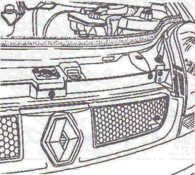
Figure 4.1. Remove the license plate, turn signals and radiator grille.

Figure 4.1. Remove the license plate, turn signals and radiator grille.


8. Unscrew the headlight mounting bolts and disconnect the wiring connectors from the headlights (figure 4.2).
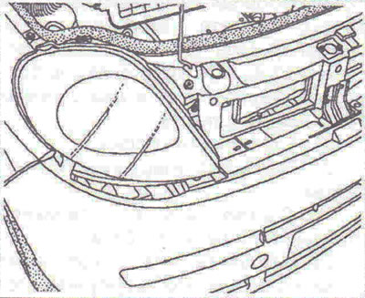
Figure 4.2. Unscrew the headlight mounting bolts and disconnect the wiring connectors from the…

Figure 4.2. Unscrew the headlight mounting bolts and disconnect the wiring connectors from the headlights.


9. Remove the bumper (figure 4.3a, b).
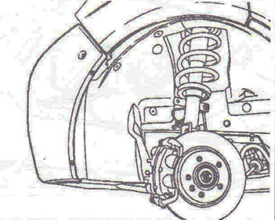
Figure 4.3a. Remove the bumper.
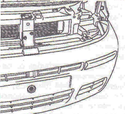
Figure 4.3a. Remove the bumper.


Figure 4.3b. Remove the bumper.

Figure 4.3b. Remove the bumper.


10. Remove the power steering fluid reservoir.

11. Remove the hood locking mechanism (figure 4.4).
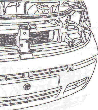
Figure 4.4. Remove the hood locking mechanism.

Figure 4.4. Remove the hood locking mechanism.


12. Disconnect the air ducts from the charge air cooling radiator, two tubes from the condenser, the upper hose of the cooling system radiator, and the wiring connectors from the fan motor.


13. Remove the expansion tank.

14. Remove the boost pressure control solenoid valve.

15. Disconnect the wiring connector from the pre-heating and post-heating control unit.

16. Remove the engine control unit cover and unscrew its mounting bolts. Disconnect the wiring connectors from the engine control unit.

17. Disconnect the fuse box from the junction box.

18. Disconnect the wire harness from the connector.

19. Disconnect the fuel shut-off sensor wiring connector.

20. Disconnect the hydraulic transmission control on the master cylinder, transmission rods (figure 4.5).
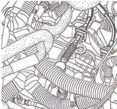
Figure 4.5. Disconnect the hydraulic transmission control on the master cylinder, transmission rod.

Figure 4.5. Disconnect the hydraulic transmission control on the master cylinder, transmission rod.


21. Unscrew bolt 1 securing the hydraulic power steering tube to the cross beam, remove the lower cross beam 2, unscrew the bracket mounting nuts and remove the engine suspension rod (figure 4.6).
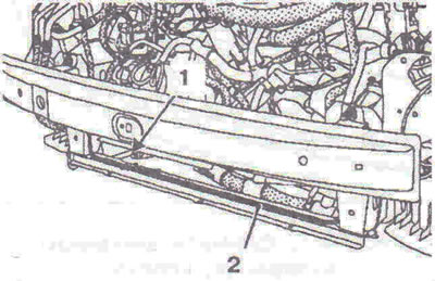
Figure 4.6. Unscrew bolt 1 securing the hydraulic steering tube to the cross member, remove the…

Figure 4.6. Unscrew bolt 1 securing the hydraulic steering tube to the cross member, remove the lower cross member 2.


Right side of the car


22. Remove the brake caliper and attach it to the suspension spring, ABS sensor, stabilizer link, unscrew the lower ball joint nut (use a socket wrench at X = 22 mm if necessary to lock the ball joint), unscrew both bolts securing the gearbox flange to the bracket, remove the tie rod end using the T.Av. 476 tool and two shock absorber support bolts (figure 4.7).
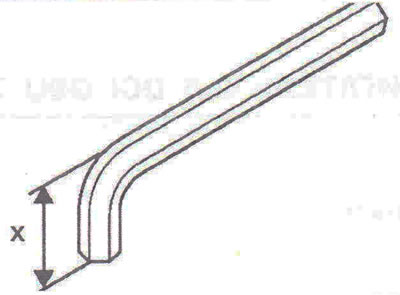
Figure 4.7. Socket wrench for X = 22 mm.

Figure 4.7. Socket wrench for X = 22 mm.


23. Disconnect the axle shaft.

24. Remove the hub together with the axle shaft.

Left side of the car


25. Remove the brake caliper and attach it to the suspension spring, ABS sensor, unscrew the lower ball joint nut (use a socket wrench with X = 22 mm if necessary to lock the ball joint), remove the tie rod end using the T.Av. 476 tool, unscrew the three axle boot bolts and the two shock absorber support bolts.

26. Disconnect the axle shaft.

27. Remove the hub together with the axle shaft.

28. Remove the fuel tank filler cap.

29. Loosen the fuel tank mounting bolts to gain access to the fuel level sensor.

30. Disconnect the fuel level sensor wiring connector 3 (figure 4.8).
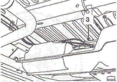
Figure 4.8. Disconnect wiring connector 3 from the fuel level sensor.

Figure 4.8. Disconnect wiring connector 3 from the fuel level sensor.


31. Disconnect the wiring harness from the battery support.

32. Disconnect the air duct from the turbocharger, the hydraulic power steering tubes from the steering gear.

33. Disconnect the pipe from the heater radiator using tool Mot. 1448 (figure 4.9).

34. Disconnect the wiring connector from the fuel heater, the fuel intake line from the high-pressure fuel pump, and the fuel drain line from the fuel temperature sensor.
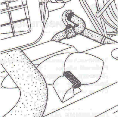
Figure 4.9. Disconnect the pipe from the heater radiator using tool Mot. 1448.

Figure 4.9. Disconnect the pipe from the heater radiator using tool Mot. 1448.


35. Unscrew the bolts securing the crossbar 4 and remove it (figure 4.10). Disconnect the ground wire from the transmission.
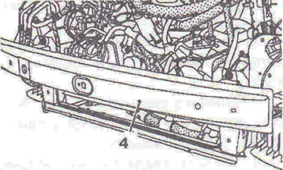
Figure 4.10. Unscrew the bolts securing the crossbar 4 and remove it.

Figure 4.10. Unscrew the bolts securing the crossbar 4 and remove it.


36. Place the Mot. 1390 hoist under the engine (figure 4.11).
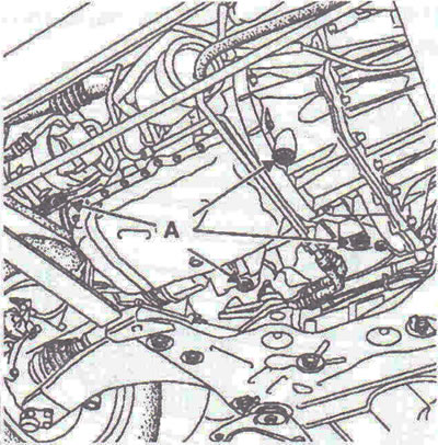


Figure 4.11. Position the Mot. 1390 hoist under the engine.

Figure 4.11. Position the Mot. 1390 hoist under the engine.


37. Remove the right engine mount (figure 4.12).

Caution: Before completely loosening the engine mount bolts, make sure that the engine is securely fastened to the lift.
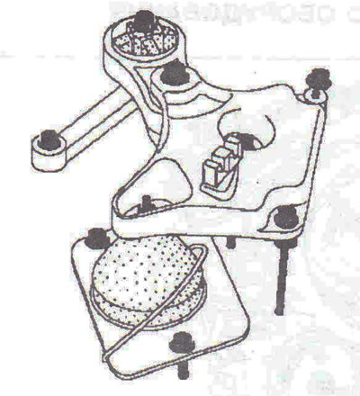

Figure 4.12. Remove the right engine mount.

Figure 4.12. Remove the right engine mount.


38. Unscrew the nut and knock out bolt 5 with a hammer (figure 4.13).
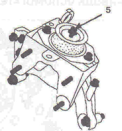
Figure 4.13. Unscrew the nut and knock out bolt 5 with a hammer.

Figure 4.13. Unscrew the nut and knock out bolt 5 with a hammer.


39. Remove the engine together with the gearbox.

Installation


40. Installation is carried out in the reverse order of removal.

Tightening torques


  • Shock absorber mounting bolt - 180 Nm.
  • Brake caliper mounting bolt - 35 Nm.
  • Tie rod end mounting nut - 37 Nm.
  • Lower ball joint nut - 105 Nm.
  • Axle shaft boot mounting bolt - 105 Nm.
  • Engine mount rod mounting bolt: to subframe - 105 Nm, to engine - 280 Nm.
  • Upper engine mount arm mounting bolt - 105 Nm.
  • Engine mount travel limiter mounting bolt to the body - 44 Nm.
  • Engine mount cover mounting bolt to engine - 65 Nm.
  • Travel limiter mounting nut - 44 Nm.
  • Wheel mounting bolts - 142 Nm.


This article is available at russian, bulgarian, belarusian, ukrainian, serbian, croatian, romanian, polish, slovak, hungarian
Checking the article: Meshcheryakov Damir

Share information:

Previous articles
Opel Vivaro A: Diesel engine G9U
Next articles

Oil pressure
Engine specifications
Removal and installation the pallet
Removal and installation the oil pump
Removal and installation the accessory drive belt
Removal and installation the timing belt
Removal and installation the air filter
Removal and installation the air distributor


See similar ones from other Opel car manuals:
▶ Engine and gearbox mounts Opel Omega B (1993-1999)
▶ Removal and installation of a gasoline engine together with… Opel Vectra B (1995-2002)
▶ Engine bay — 1.4L C 14 NZ engine Opel Astra F (1991-1998, petrol)
▶ Starting the engine from an auxiliary power source Opel Corsa B (1993-2000)
▶ Engine compartment fuse box Opel Insignia A (2008-2017)
Link to this page in different formats

Visitor comments


No comments yet


How much will 35 + 22 =


Vivaro A (2001-2014) 
  • General information
  • User manual
  • Power unit
  • Petrol engine F4R
  • Diesel engine F9Q
  • Diesel engine G9U
  • Transmission
  • Clutch and drive shafts
  • Manual gearbox
  • Chassis
  • Front suspension
  • Rear suspension
  • Brake system
  • Body
  • Exterior
  • Interior
  • Electrical equipment
  • Heating and ventilation
  • Air conditioner
  • Equipment and devices
  • Electrical diagrams
Ascona C (1981-1988) 
  • General information
  • Maintenance
  • Power unit
  • Gasoline engines
  • Diesel engines
  • Cooling system
  • Fuel and exhaust system
  • Contact ignition system
  • Contactless ignition system
  • Transmission
  • Clutch
  • Mechanical gearbox
  • Automatic gearbox
  • Drive shafts
  • Chassis
  • Steering
  • Brake system
  • Car suspension
  • Body
  • Exterior
  • Interior
  • Doors and windows
  • Electrical equipment
  • Equipment and devices
  • Power devices
  • Electrical circuits
Frontera B (1998-2004) 
  • General information
  • User manual
  • Maintenance
  • Power unit
  • Petrol engines 2.2 l
  • Petrol engines 3.2 l
  • Diesel engines 2.2 l
  • Cooling system
  • Fuel system (petrol)
  • Fuel system (diesel)
  • Ignition system
  • Transmission
  • Clutch
  • Manual gearbox MUA5C
  • Automatic gearbox 4L30E
  • Chassis
  • Suspension and axles
  • Steering
  • Brake system
  • Body
  • Exterior
  • Interior
  • Doors, locks and windows
  • Heating and air conditioning
  • Electrical equipment
  • Power devices
  • Equipment and devices
  • Lighting and signaling
  • Electrical diagrams
Frontera A (1991-1998, petrol) 
  • General information
  • Introduction to guide
  • User manual
  • Maintenance
  • Power unit
  • Engine repair
  • Lubrication system
  • Cooling system
  • Power and exhaust system
  • Engine electrics
  • Transmission
  • Clutch
  • Mechanical gearbox
  • Cardan shafts
  • Chassis
  • Brake system
  • Front suspension
  • Rear suspension
  • Steering
  • Body
  • Repair and care
  • Electrical equipment
  • Equipment and devices
  • Electrical circuits
OpelBook.ru © 2017–2026 · Mobile version · · Sitemap: EN BG BY UA RS HR RO PL SK HU · Feedback · Site search
Astra F, petrol · Astra G, petrol · Astra G · Astra H · Astra J, petrol · Corsa B · Corsa C, petrol · Corsa C · Insignia A · Kadett D · Kadett E · Omega A · Omega B · Omega B2 · Vectra A, petrol · Vectra A · Vectra B, petrol · Vectra B · Vectra C · Zafira A, petrol · Frontera A, petrol · Frontera B · Ascona C · Vivaro A ·
We want your visit to be comfortable 🤝! We use cookies 🍪 to make that happen.