


Contents: Removal ⬇ Installation ⬇
Removal
Raise the vehicle and support it on supports.
Remove the front wheel from the corresponding side.
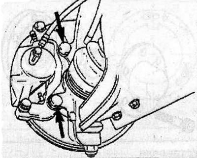
Remove the 2 caliper mounting bolts, lift the caliper up and secure it to the front suspension strut with soft wire.
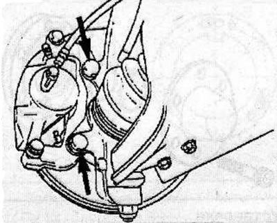
Remove the front wheel speed sensor (ABS) from the steering knuckle.
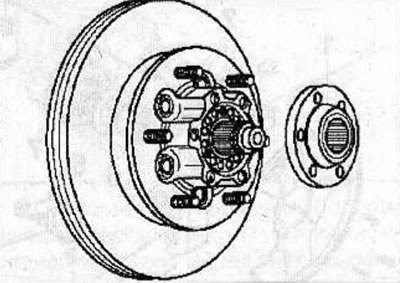
Remove the hub drive flange from the drive shaft (see the relevant chapter).
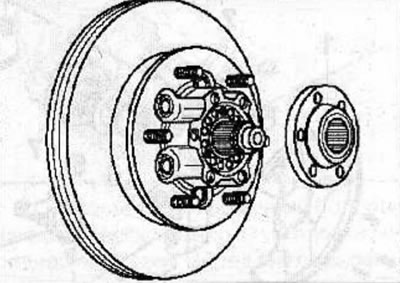
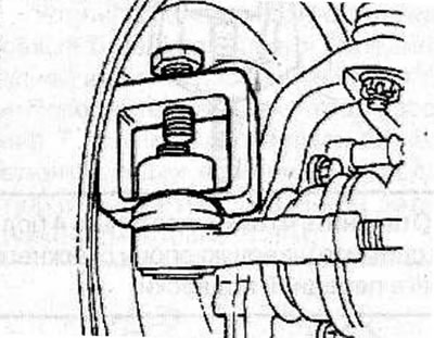
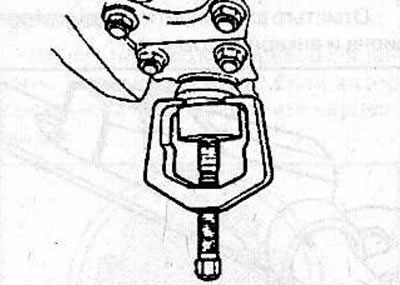
Loosen the nut securing the ball joint pin of the steering rod end to the steering knuckle. Using the KM-787 puller, push the ball joint pin of the steering rod end out of the steering knuckle.
Remove the cotter pin, unscrew the nut and use the appropriate KM-787 puller to remove the upper ball joint from the steering knuckle.
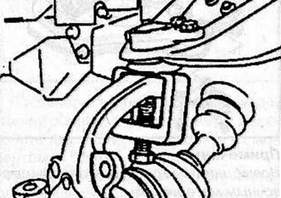
Remove the cotter pin, unscrew the nut and use a suitable puller to remove the lower ball joint from the steering knuckle.
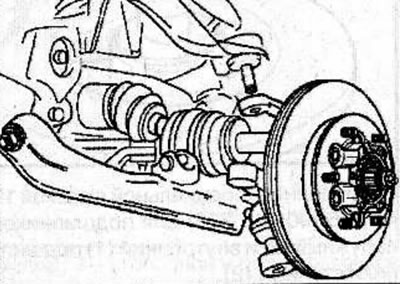
Remove the hub with the steering knuckle from the drive shaft.
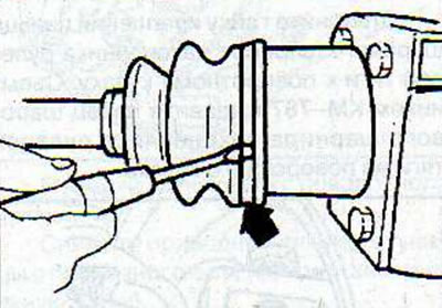
Use a screwdriver to remove the clamp securing the protective cover of the outer CV joint of the drive shaft.
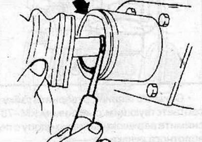
Remove the retaining ring (arrow) from the CV joint housing.
Remove the drive shaft with balls and cage from the CV joint housing.
Use a screwdriver to remove the six balls from the clip.
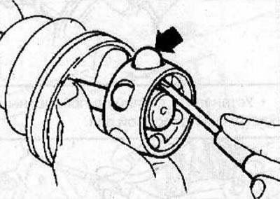
Rotate the separator a distance equal to half the ball diameter and move it onto the drive shaft.
Remove the retaining ring from the sleeve and remove the sleeve from the drive shaft.
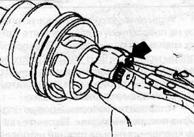
Remove the separator from the drive shaft.
Use a screwdriver to remove the small clamp securing the protective cover of the outer CV joint of the drive shaft and, sliding it along the shaft, remove the protective cover.
Installation
Clean all drive shaft parts thoroughly.
Check the CV joint components for wear and damage.
Fill the outer CV joint protective boot with special lubricant 19 41 521 (90 094 176), when doing this, add half the recommended amount of lubricant.
Wrap the splines of the drive shaft with adhesive tape, slide the protective boot onto the shaft and secure it with a clamp, making sure that the protective boot is not deformed or warped. The installation direction of the protective cover mounting clamp is shown in the figure, with the arrow pointing to the front of the vehicle.
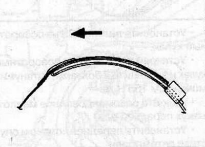
Install the cover onto the inside of the drive shaft.
Install the separator (arrow) on the drive shaft, installing it from the side with the smaller diameter of the separator.
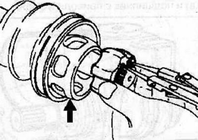
Install the collar onto the drive shaft and secure it with a new snap ring.
Use your fingers to install 6 balls (arrow) into the separator, aligning the windows in the separator with the tracks of the balls in the cage by turning the housing a distance equal to half the diameter of the ball.
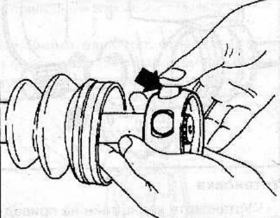
Install the drive shaft assembly with the cage, separator and balls into the CV joint housing and secure with a new retaining ring, positioning the ends of the retaining ring so that they are located between the two ball grooves.
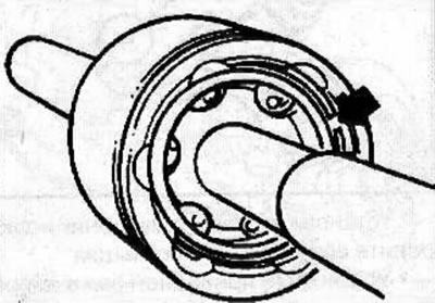
Fill the outer CV joint with special lubricant 19 41 521 (90 094 176), while adding the remaining half of the recommended amount of lubricant.
By squeezing the protective cover, set the CV joint length to 171 mm, while using a screwdriver to lift the protective cover, release the air from underneath it.
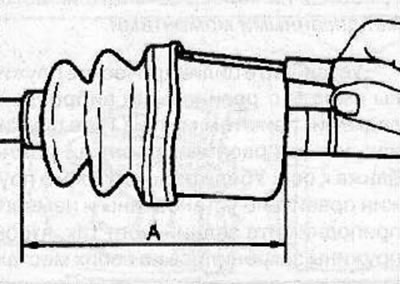
Secure the protective cover with a large clamp, making sure that the protective cover is not deformed or warped. The installation direction of the large clamp for fastening the protective cover is the same as that of the small clamp.
Install the wheel hub with the steering knuckle onto the drive shaft.
Install the upper ball joint onto the steering knuckle. Tighten the upper ball joint pin mounting nut to a torque of 98 N·m and turn it until the first alignment of the locking hole with the slot in the crown nut. Install a new cotter pin.
Install the lower ball joint onto the steering knuckle. Tighten the lower ball joint pin mounting nut to a torque of 147 N·m and turn it until the first alignment of the locking hole with the slot in the crown nut. Install a new cotter pin.
Install the ball joint pin of the tie rod end into the steering knuckle and secure it with a nut.
Install the hub drive flange onto the drive shaft (see the relevant chapter).
Install the ABS sensor on the steering knuckle.
Install the caliper on the steering knuckle and secure with 2 bolts, tightening them to a torque of 155 Nm.
Fill the front axle housing with the recommended oil.
Install the front wheel and lower the vehicle.
Visitor comments