


Contents: Control Panel ⬇ Air intake control lever ⬇ Fan control lever ⬇ Temperature mode selection lever ⬇ Air distributor control lever ⬇ Ventilation nozzles ⬇ Selection of operating modes of the…⬇ Air conditioning system ⬇
Control Panel
The required air temperature in the car interior is achieved in a very short time by mixing cold and hot air flows. Engine speed has virtually no effect on the efficiency of the system.
The air flow parameters are determined by the vehicle speed and the choice of the heater fan speed mode. The need to turn on the fan only arises at low speeds.
Outside air is drawn into the passenger compartment through an air intake located directly in front of the car's windshield - make sure that the air intake grille is not clogged with debris or snow.
Air intake control lever
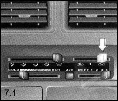
The choice of the source of air supplied to the passenger compartment is carried out by moving the air intake control lever (upper right) on the control panel.
Moving the lever to position (2) switches the air intake flap to suck outside air into the passenger compartment through the ventilation system. When the lever is moved to position (1), the closed air circulation mode is activated, maintained by the rotation of the heater fan impeller - prolonged stay of the system in the closed circulation mode can lead to fogging of the glass, so if possible, you should open the window as soon as possible, allowing access to outside air.
Fan control lever
The intensity of air supply to the ventilation system can be increased by turning on the 4-speed heater fan.
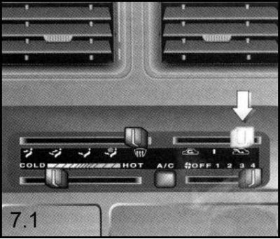
The fan speed mode is switched on and selected by moving the lower right lever on the control panel.
When the lever is set to the OFF position, the fan turns off. Position 1 corresponds to low-speed fan rotation mode; position 2 is intermediate between low and medium speed modes; position 3 corresponds to the middle mode between medium-speed and high-speed; and finally, moving the lever to position 4 switches the fan to high speed mode.
Note: The fan can only operate when the engine is running.
Temperature mode selection lever
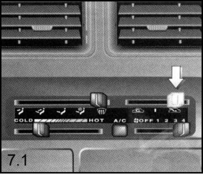
The temperature of the air supplied to the passenger compartment is controlled by changing the position of the lower left lever of the control panel.
Moving the lever towards the inscription "HOT" (Hot) leads to an increase in the air temperature, towards "COLD" - to a decrease.
Air distributor control lever

The direction of air flow to different areas of the cabin is selected using the upper left lever on the control panel.
When the lever is set to position (5), air is supplied to blow the windshield; by selecting position (4) air is supplied simultaneously to blow the glass into the footwells; when the lever is moved to position (3), air begins to flow only to the foot wells; position (2) corresponds to the air supply mode both to the upper part of the cabin and to the footwells; when position (1) is selected, air is supplied only to the upper part of the passenger compartment.
Ventilation nozzles
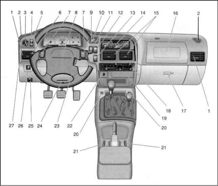
Location of components and controls for auxiliary systems in the instrument panel/lower console: 1 - Side ventilation/heating nozzles; 2 - Door glass blower nozzles; 3 - Headlight switch; 4 - Front fog light switch (if provided); 5 - Rear fog light switch; 6 - Rod switch for direction indicators, headlight flashing, switching between low and high beam headlights; 7 - Sound signal on/off buttons; 8 - Driver's seat airbag (if provided); 9 - Rod switch for windshield wipers/washers, headlight lens washers (if provided) and rear window washer (if provided); 10 - Hours; 11 - Rear window defroster switch; 12 - Hazard warning switch; 13 - Plug; 14 - Radio receiver (if provided); 15 - Central ventilation/heating nozzles; 16 - Passenger airbag (if provided); 17 - Instrument panel storage compartment; 18 - Control panel for interior heating/ventilation systems; 19 - Ashtray; 20 - Front seat heating switches (if provided); 21 - Electric window switches (if provided); 22 - Cigarette lighter; 23 - Ignition/steering column lock; 24 - Knee level ventilation/heating nozzle; 25 - Bonnet lock release handle; 26 - Adjusting the position of the headlights depending on the vehicle's load level; 27 - Fuse box mounting
Central ventilation nozzles
These nozzles are located in the central part of the vehicle's instrument panel directly above the heating/ventilation control panel (15 in the illustration Location of components and controls for auxiliary systems in the instrument panel/lower console) and serve to supply cold or heated air to the upper part of the passenger compartment, depending on the selected temperature mode.
The air supply intensity can be increased by turning on the heater fan.
By changing the position of the nozzle grille louvers, the flow direction can be adjusted according to the wishes of the driver or front passenger.
Side ventilation nozzles
At the driver's or front passenger's request, air flow from the vents located at the edges of the instrument panel (1 in the illustration Location of components and controls for auxiliary systems in the instrument panel/lower console) can be directed either to the central part of the passenger compartment or to blow air onto the door windows and panels to create a layer of warm air along them in the cold season.
Article published on the website: OpelBook
To change the direction of the flow, turn the nozzle grille louvers accordingly.
Door window blower nozzles
These nozzles are also located on the sides of the instrument panel, but above the side ventilation nozzles (2 in the illustration Location of components and controls for auxiliary systems in the instrument panel/lower console) and provide additional blowing of the front door windows of the car, mainly in the area where the rear-view mirrors are located.
Knee level interior ventilation nozzle
The nozzle is designed to blow air onto the driver's knees and is located at the bottom of the instrument panel under the steering wheel (24 in the illustration Location of components and controls for auxiliary systems in the instrument panel/lower console).
It is possible to adjust the direction of the air flow from this nozzle in the vertical plane by turning the grille blinds.
The flow intensity can be increased by turning on the heater fan.
Air supply nozzles for foot wells
The nozzles are located at the base of the heater assembly. The flow intensity can be increased by turning on the fan.
Selection of operating modes of the interior heating/ventilation systems
Turning on the cabin ventilation mode
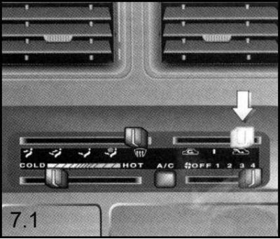
1. Set the temperature mode selection lever to the "COLD" position and the air intake control lever to position (2).
2. Turn on the heater fan.
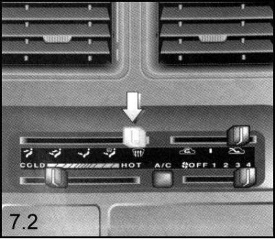
3. Using the air distributor control lever, select the required direction of air supply to the passenger compartment (1), (2) or (3).
Selecting the interior heating mode
The intensity of air supply is determined by the choice of fan speed (lower right lever on the control panel).
The required temperature mode is set by the lower left lever on the control panel.
The comfort of the climate in the passenger compartment is largely determined by the choice of direction of warm air supply.

The most favorable mode for a person's well-being is considered to be the "feet warm, head cold" mode, which is achieved by setting the air distributor control lever to position (1) or (2) with the temperature selection lever in the middle position.
1. To warm up the footwell space, move the temperature mode selection lever to the "HOT" position and the air distributor control lever to position (3).
2. Turn on the high speed mode of the heater fan.
Switching on the glass blowing/heating mode
1. Move the temperature selection lever to the "HOT" position.
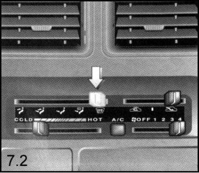
2. Depending on the specific tasks, set the air distributor control lever to position (5) or (4).
3. Switch the fan to high speed operation mode (4).
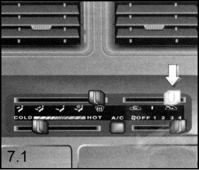
4. Move the air intake control lever to position (1).
5. Turn on the rear window heating (see below).
Air conditioning system
If the vehicle is equipped with an air conditioning system, the latter can only function when the engine is running and the heater fan is switched on at any speed.
The design of the air conditioner determines the need for its operation in conjunction with the heating and ventilation systems of the vehicle interior. Air conditioning allows you to achieve the most favorable climate conditions for the well-being of passengers in the car, regardless of the weather conditions outside.
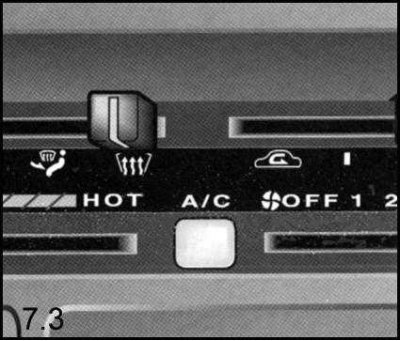
1. To turn on the air conditioning system, press the button located in the center of the lower part of the control panel for the heating/ventilation systems of the passenger compartment - the indicator lamp inside the button should light up.
The system is turned off by pressing the same button again.
When the air conditioner is turned on, fuel consumption increases slightly, so you should not get carried away with its use unless absolutely necessary.
Rear window heating
Note: Rear window heating is only possible when the ignition is on.
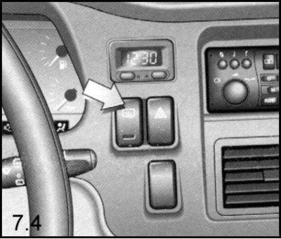
The rear window heating is switched on using a button paired into one block with the hazard warning light switch. When the heating is on, the indicator light inside the button lights up.
The rear window defroster element is an energy-intensive consumer and should therefore be switched off as soon as the glass becomes sufficiently transparent.
Electric heated front seats
Turning on the electric heating of each of the front seats of the car (if such is provided) is carried out by a separate button. Both buttons are located on the sides of the car's central console. When the heater is turned on, a control lamp inside the corresponding button lights up.
Visitor comments