


Steering without power assistance.
1. Remove the air conditioner.
2. If you have a headlight cleaning system installed, release the fluid reservoir and move it to the side.
3. Disconnect the battery ground cable.
4. Working from the center of the steering rack housing, remove both bolts and remove the bolt stops and gasket plate (photo).
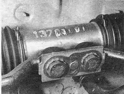
Photo 4.4 Connection of the rod to the steering rack.
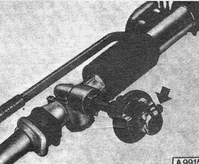
Figure 8.4 Steering gear alignment diagram - left side. A= 325.0 mm (12.8 inches).
5. If the model is equipped with a steering shock absorber, disconnect the shock absorber brackets from the steering housing and remove the shock absorber.
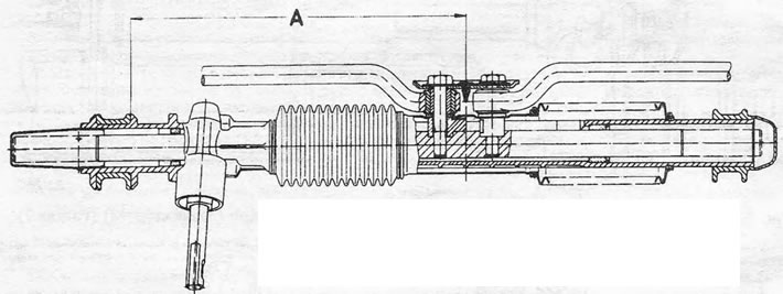
Figure 8.5 Location of the upper clamping bolt of the flexible coupling with the steering gear centered - indicated by the arrow (left side)
6. Pull the cardboard panel out from under the dashboard to access the steering column shaft flexible coupling.
7. Place the steering wheel and front wheels in the "straight ahead" position.
8. Unscrew the two clamping bolts on the flexible coupling at the base of the steering column shaft (photo).
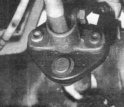
Photo 4.8 Upper clamping bolt of flexible coupling (indicated by the arrow).
9. Remove the flexible coupling upward from the gear.
10. Unscrew the steering column mounting brackets and remove the rack and pinion housing through the front right wheel arch (photo).
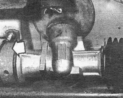
Photo 4.10 Rack and pinion with mounting bracket (indicated by the arrow).
11. Assembly is carried out in the reverse order, but before connecting the flexible coupling to the gear, the steering must be centered as follows.
12. Jack up the front of the vehicle and turn the steering gear until the distance between the center of the shim plate and the rib on the bracket is as shown (Figure 8.4).
13. Place the steering wheel in the "straight ahead" position.
14. If you had a steering shock absorber, screw it to the steering housing and tighten the bolts to the specified torque value.
15. Push the flexible coupling down and connect it to the gear, then tighten the coupling bolt to the specified torque value.
16. The top clamp should now be in a position where the clamp bolt is parallel to the steering housing. If this is not the case, this indicates that the pinion is not in phase with the rack and pinion and the components need to be moved in relation to each other as indicated in Section 6.
17. Check that the concave end of the mounting bracket faces downward when the steering is installed.
18. If the pinion cap has been disturbed, make sure that its recess aligns with the rib on the steering housing.
Power steering.
19. The operations are similar to those just described for manual steering, except that the jet pipes (pressure tubes) and the return pipes must be disconnected before the disassembly procedure.
20. Disconnect the pressure tube coupling and loosen the return hose ring, then separate the couplings (photo).
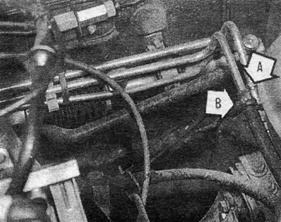
Photo 4.20 Pressure tube coupling (A) and return hose ring (B) of power steering gear.
21. Allow fluid to drain from open couplings, then wrap couplings in small plastic bags or tape them to prevent dirt from entering.
22. When reinstalling the steering, center it by counting the number of turns from stop to stop as the pinion shaft turns. Then bring the steering to the desired state by turning the pinion shaft from the extreme position by half the counted number of revolutions.
23. Install the flexible coupling onto the gear shaft (the steering is still centered), so that the upper clamp bolt is positioned horizontally and on top of the gear shaft.
24. Reconnect the couplings, then fill and bleed the system as described in Section 13.
Visitor comments