


Please note: The steering column can be disassembled and assembled either while it is installed on the vehicle or while it is removed; the procedure remains similar. The procedure described here applies to the column installed on the machine.
1. Remove the steering wheel from the steering shaft while the unit is removed from the vehicle as described previously (Section 8).
2. Remove the column switches (Section 9, paragraph 2).
3. Disconnect the mounting bracket from the switches.
4. Remove the safety plugs and remove the column switch housing by turning it to the left and pulling it (photo).
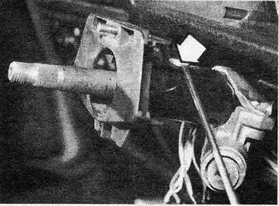
Photo 10.4A Remove the steering column switch fuse plugs (indicated by arrows)
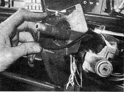
Photo 10.4B....turn the switch assembly counterclockwise and remove it from the column
5. The double row ball bearing can be removed from its housing by first separating the two gripping devices. Remove the bearing using a piece of pipe as a punch.
6. Install the new bearing by performing these operations in reverse order. Please note the pusher gasket A (Figure 8.18).
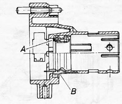
Figure 18 Section of the switch housing
7. Set the locking cylinder to the "P" position and press the locking plunger using a thin rod. Remove the mechanical component of the switch.
8. Remove the two screws and remove the switch electrical component.
9. Remove the trim from under the instrument panel and unscrew the upper pinch bolt from the flexible coupling. Remove the steering shaft from the column tube.
10. When assembling, first insert the shaft into the column tube and then engage the lower part of the shaft with the flexible coupling, making sure that the recess in the shaft matches the bolt hole in the clamp.
11. Attach a temporary plastic centering gasket to the base of the column tube.
12. Install the locking cylinder and ignition shutter.
13. Install the switch housing into the column tube using new safety plugs.
14. Install the direction indicator and wiper switches and install the mounting bracket.
15. Install the column casing.
16. Install the gasket and spring onto the upper shaft bearing.
17. Install the steering wheel and tighten the nut to the specified torque value using a new locking plate.
18. Pull the steering wheel/shaft upward until it contacts the upper bearing of the shaft.
19. While holding this position, tighten the clutch clamp bolt.
20. Remove the temporary plastic centering spacer.
21. Reinstall the instrument panel trim. Check the steering centralization as specified in Section 4.
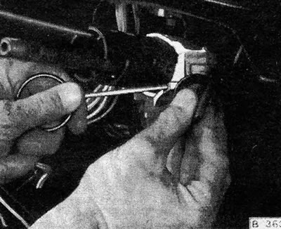
Figure 8.19 Using the rod to press the steering column retaining plunger - left side
Visitor comments