
Manual steering.
1. Remove the steering from the car as previously indicated.
2. Clean off external dirt.
3. Remove the bellows and cuff of the case.
4. Remove the slider and guide from the gear
5. Release the compressed steel lock nut from the rack adjusting screw.
6. Unscrew and remove the adjusting screw and remove the coil spring, oil seal and shock absorber slide.
7. Pull the locking ring off the gear nut, unscrew the nut and remove the oil seal.
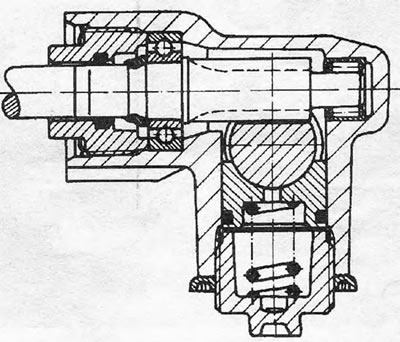
Pic. 8.7 Cross-section of gear and rack shock absorber
8. Remove the rack and pinion.
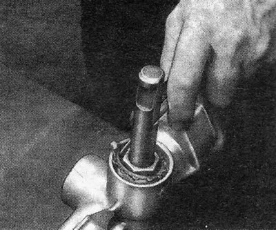
Pic. 8.8 Removing the steering gear locking ring - left side
9. Press the cap from the end of the case using a long rod (Pic. 8.9).
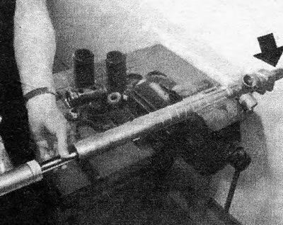
Pic. 8.9 Removing the rack case cap - indicated by arrow (left-hand side)
10. Further disassembly is not possible. If the rack bushings or needle bearing are worn, replace the entire case. The gear can only be replaced together with the ball bearing.
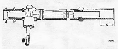
Pic. 8.10 Notch on pinion shaft located furthest from the longer tubular portion of the rack housing - left side
11. Clean off old grease and lubricate internal components with specified grease. Lubricate with 50 grams (1 3/4 oz) lubricant between the rack bushings on the inside of the case.
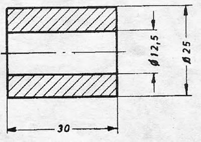
Pic. 8.11 Dimensions of temporary fixtures (Dimensions in mm).
12. Insert the rack into the case and position it so that the end farthest from the gear is in the position shown in Fig. 8.10.
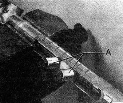
Pic. 8.12 Adjustment devices (A), screwed to the steering rack - left side
13. Now insert the pinion so that when its gear finally engages the teeth of the rack, the slot on the pinion shaft will be at right angles to the rack and with respect to distance A as indicated in Fig. 8.10.
14. Lubricate the pinion ball bearing with the specified grease and tighten the pinion nut to the specified torque. Install the new nut retaining ring by holding it in place with a piece of pipe.
15. Now you need to adjust the steering. To do this, make two fixtures following the dimensions shown in Fig. 8.11. Screw the slider, guide and fabricated fixtures to the rack using the rod eye mounting bolts (Pic. 8.12).
16. Insert the rack damper slider and coil spring into their hole and tighten the adjusting screw until you feel some resistance.
17. Loosen the adjusting screw 1/8 to 1/4 turn and check that the rack moves freely along the entire length of its feed.
18. Without disturbing the position of the adjusting screw, install the compressed steel lock nut and tighten it to the specified torque.
19. Hammer a new end cap into the case, install the bellows, and remove the temporary fixtures and rod eye bolts from the rack.
20. Install the gear cap fasteners and seal as indicated in Section 5, paragraphs 5 and 6.
21. Check the steering alignment as indicated in Section 4, paragraphs 12 - 16. If the pinion-rack gear engagement is not made correctly, the pinion must be removed and moved to correct the alignment.
22. After installing the steering on the machine, make a test drive along a route with corners and turns. The steering should exhibit a distinct self-centering action after the steering block has been applied. If this is not the case, it means that the rack shock absorber has been over-tightened and needs to be adjusted.
Power steering.
23. Inspection of power steering is not recommended. Any malfunction or wear means the entire assembly needs to be replaced.
Visitor comments