


2. Disconnect and slide back the water-resistant plastic shield to gain access to the lock cylinder.
3. Disconnect the control lever from the lock lever (see photo 18.3).
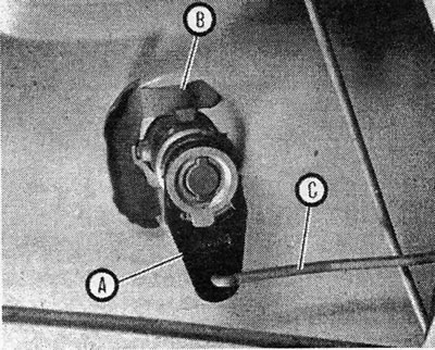
Photo 18.3 Lock cylinder - view from inside the door; the lever (A), spring clamp (B) and control lever (C) are shown
4. Disconnect the fork spring clip and pull out the lock cylinder assembly.
5. To disassemble, insert the ignition key into the lock, and then insert a screwdriver between the casing and the lever to remove the spring clip (see Figure 11.26).
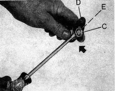
Figure 11.26. Disconnecting the lock cylinder housing from the lever C - casing E - spring clamp; D - lever
6. Disassemble the parts, noting the sequence of their installation (see Figure 11.27).
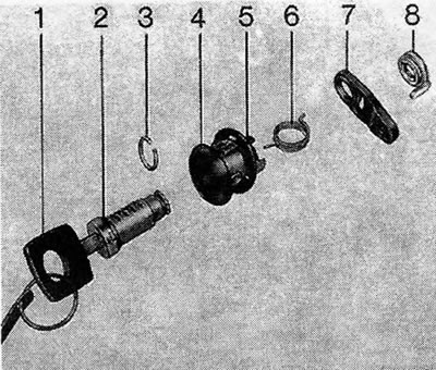
Figure 11.27. Detailed image of the lock cylinder: 1. Key; 2. Cylinder; 3. Spring clamp 4. Casing 5. Gasket; 6. Spring; 7. Lever; 8. Rear end.
7. Reassembly is carried out in the reverse order, but note that the ends of the spring must be crossed as shown in Figure 11.28, and the correct position of the lever in relation to the casing must be maintained. Use a new spring clip.
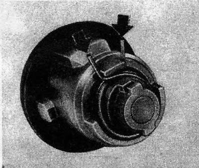
Figure 11.28. Correctly positioned ends of the lock cylinder spring are indicated by arrows
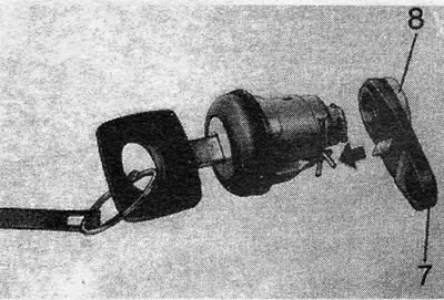
Figure 11.29. Position of the cylinder lock in relation to the casing - rear end (8) and lever (7) shown
Visitor comments