


2. Turn the freewheel hub to the "FREE" position.
3. Remove six bolts.
4. Remove the housing and coupling.
5. Remove the snap ring and spacers from the end of the drive shaft.
6. Remove six bolts.
7. Remove the hub lock
8. Press the coupling away from the housing.
Original posted on the website: www.opelbook.ru
9. Turn it clockwise.
10. Remove the test button, pressure spring, locking ball and locking spring from the housing.
11. Remove the leash and retaining ring from the coupling by turning the ring counterclockwise.
12. Remove the locking ball and locking spring from the control button.
13. Remove the X-ring from the housing.
14. Remove the hub lock
15. Check all parts for wear and replace if necessary.
16. The above mentioned special grease "HD2" is used for assembly.
17. The following parts are lubricated: both surfaces of the insert ring, the inner surface of the ring, the splined surface of the hub housing, the X-ring and the contact surfaces of the control button and housing, the locking ball and the locking spring.
Now reassemble the hub lock:
1. Install the X-ring, control button, locking ball and locking ring.
2. Install the retaining ring onto the housing. The locking ball must be aligned with the groove in the cover.
3. Insert the retaining spring into the coupling. The straight end of the spring must be aligned with the end of the groove cutout in the coupling.
4. Install the leash on the coupling.
5. Align the teeth of the leash with the teeth of the couplings. When doing this, check that the protrusion (A) on the leash is in line with the bent end of the spring.
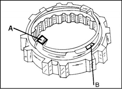
6. Place the upper spring coil leash above the sample (B). The installation diagram is shown in the illustration.
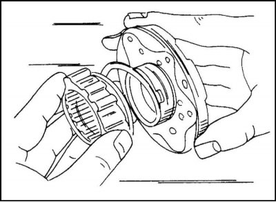
7. Install the coupling and pressure spring on the housing. This is achieved by pressing and turning left towards the button. The assembly is shown in the illustration.
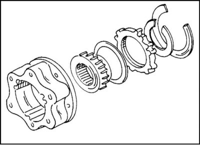
8. Assemble the hub lock by installing a new snap ring as shown.
9. Apply sealant to the mating surfaces of the hub and cover.
10. Install the lid.
11. Secure it with six bolts to a torque of 60 Nm.
12. Measure the clearance between the hub lock and the drive shaft snap ring. This is best achieved by installing an indicator on the wheel hub.
13. If the gap is beyond 0-0.3 mm, install a compensation washer. Washers with a thickness of 0.1 mm are available.
14. Install the coupling and housing onto the hub lock.
15. Align the outer teeth of the coupling with the groove on the housing.
16. Coat the contact surfaces of the housing and hub lock with sealant.
17. Tighten the mounting bolts to a torque of 12 Nm.
Visitor comments