
Removal and installation of the automatic hub lock is described below. It should be pointed out that the functioning and wear of the mechanisms in question can only be checked in a car workshop.
1. Set the transfer case gear selector to position "2H"
2. Move the car about a meter forward and backward to release the hub lock.
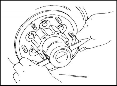
3. Further disassembly is carried out in accordance with fig. Remove the six bolts and remove the cap and hub housing.
4. Remove retaining ring
5. Remove the wear washers and drive shaft coupling.
6. If there is a suspicion of a malfunction of the hub lock, it must be sent to a car repair shop for repair.
Note. With the hub lock removed, you can check the tightness of the wheel bearing. See description below.
The hub lock is installed as follows:
1. Insert inner cam and spring.
2. Direct the spring on the cam with the groove towards the steering knuckle.
3. Ensure that the cam is fully seated on the lock washer. A hammer can be used, but care must be taken not to damage the cam teeth.
4. The shaft must be fully pulled out of the hub to achieve the clearance shown below.
5. Check that the gauge is fully seated on the lock washer. To do this, put on the shaft caliber KM-747
6. As illustrated, install the KM-748 tool on the shaft and pull it out completely.
7. Measure the gap between the installed stop and the circlip groove in the drive shaft. The gap should be 0 - 0.1 mm. The gap can be adjusted by installing 0.1 mm thick washers.
8. After measuring, remove the gauge. The inner cam remains intact.
9. Lubricate the drive shaft, coupling teeth, housing and hub cover with special grease "HD2" (94 171 686).
10. Eight grams of grease is injected into the hub housing, five grams into the cover. Under no circumstances apply excess lubricant, as this may interfere with the normal operation of the coupling.
11. Install the clutch.
12. The notch in the spacer must align with the tooth on the inner cam. Align the teeth of the clutch and the inner cam by turning the drive shaft. Assembly is carried out in accordance with the illustration.
13. Install the chosen wear washers on the end of the drive shaft.
15. Insert a new circlip into the groove.
16. Check that the retaining ring is securely seated in the groove, as the hub assembly is under significant stress.
17. In auto repair shops, the tool shown in the illustration is used for this purpose.
18. Lubricate the contact points of the hub housing and the cover with sealant.
19. crank the body (easy turning means the correct choice of wear washers).
20. Put on the lid.
21. Tighten the mounting bolts to a torque of 60 Nm.
Visitor comments