


2. Position the steering column so that the column lock release lever is accessible and unbolt the handle.
3. Press the upper steering column trim panel in the direction indicated by the arrow (see accompanying illustration) and pull up at the same time. Separate the top trim panel from the bottom and remove it.
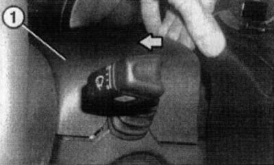
23.3. Removing the upper panel (1) of the steering column trim
4. Turn the top 2 inside out (see illustration 23.4a) and one lower (see illustration 22.4b) mounting screws and remove the lower steering column trim panel.
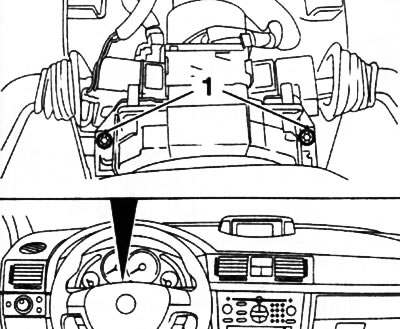
23.4a. Upper screws (1) for securing the lower steering column trim panel |
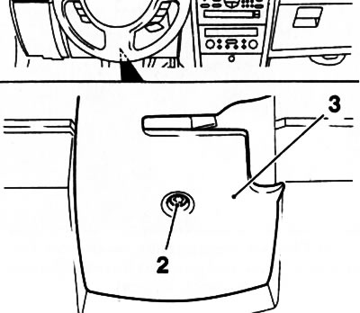
23.4b. Lower screw (2) for fastening the lower panel (3) of the steering column trim |
5. Press the locks (arrows A) and pull the lever of the corresponding steering column switch out of the contact block (see accompanying illustration). Disconnect the electrical wiring connector.
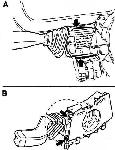
23.5 Removing (A) and installing (B) the steering column switch lever
6. Remove the second steering column switch lever in the same manner.
7. Installation is carried out in the reverse order of removal. Make sure that during installation the lever guides (arrows B) (see illustration 23.5) correctly into the mounting grooves. Lubricate the lower trim panel mounting screw and the steering column lock release lever screw with locking compound (for example, Loctite 243).
Visitor comments