


2. On Corsa C models, all the main fuses are located in a mounting block, which is mounted in the engine compartment on the left next to the expansion tank. On Meriva models, the fuses are distributed between two mounting blocks. The central (interior) mounting block is mounted in the instrument panel on the left under the panel of switches for external lighting/instrument lighting. The second mounting block is located in the engine compartment on the left side on the fluid reservoir. The blocks are equipped with removable covers.
3. To access the mounting block on Corsa C models, open the bonnet and, pressing the latches, remove the mounting block cover (see illustration 3.3a). If necessary, remove the cover over the additional fuses (see illustration 3.3b).
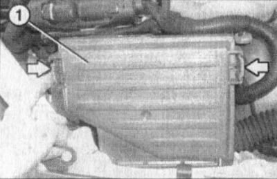
3.3a. Cover (1) of the fuse box Corsa C (using the diesel model as an example) |
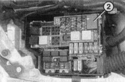
3.3b. Cover (2) of the additional fuse box (corsa C models) |
4. On Meriva models, the fuses in the passenger compartment fuse box are covered by service covers. To access the fuses, pull the upper cover by the handle and release it from the clips, then remove the lower cover.
5. In the engine compartment of Meriva models, you must first remove the cover on the fluid reservoir. Then press the side lock of the fuse box cover, pull the cover up and remove it.
6. Each individual fuse is used to protect a specific electrical circuit or several circuits. An identification card with a diagram of the location of the fuses in the mounting block is usually glued to the cover of the latter, on its inner side (see also Specifications). Note: The number and location of fuses depends on the equipment and year of manufacture of a particular model.
7. The fuses in the mounting blocks are compact in design, equipped with bayonet contacts, and, if necessary, can be easily removed from their sockets in the block. If equipped accordingly, a special clamp should be used to remove the fuses (see illustration 3.7a), which is stored in the fuse box on the right. If any of the power consumers fails, the condition of the corresponding fuse should always be checked first. The fuse body is usually made of transparent plastic, through which the condition of the working jumper can be easily determined (see illustration 3.7b).
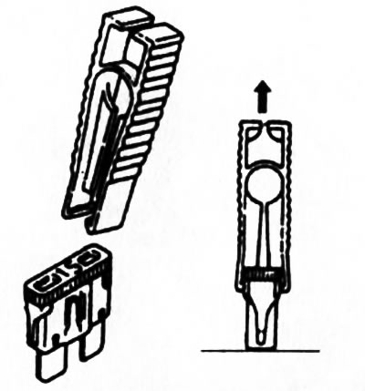
3.7a. A special clip for extracting fuses is usually attached to the inside of the fuse box cover |
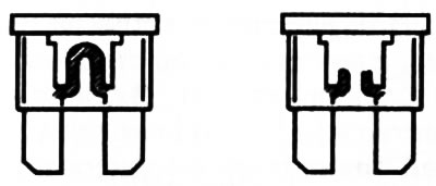
3.7b. The fact that the contact jumper of a failed fuse has burned out is easily detected by visual inspection of the element with a translucent body |
8. When replacing a blown fuse, make sure that the replacement element you prepare matches the type of the one that failed. Each electrical circuit has different operating parameters and requires a different degree of protection, so replacing a fuse designed for a certain current with one that does not match its parameters is fraught with the most serious consequences (until a fire breaks out). For the same reason, you should not use homemade wire inserts ("bugs"), Operating parameters of the fuse (rated current) are usually marked on its plastic body, in addition, color identification is additionally used (see Specifications).
9. If the new fuse also fails immediately after installation, there is no point in replacing it further - first you should identify and eliminate the cause of the overload in the circuit. In most cases, this is a short circuit in the connecting wiring caused by damage to its insulation. Spare fuses are placed directly in the mounting blocks in special free blocks (see accompanying illustration), in some configurations spare fuses can also be attached to the back of the cover of the mounting block. It is recommended to always have a spare fuse in the car and update it in a timely manner.
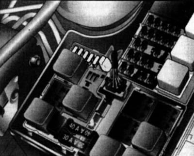
3.9. Spare fuses (for example, the Corsa C model)
10. After completing work on electrical equipment, replace the cover of the corresponding mounting block and check the tightness of the fit and fixation of the cover.
Visitor comments