


Contents: Electronic control unit ⬇ Control switch ⬇ Door lock control motor ⬇ Rear liftgate/trunk lid lock control…⬇ Fuel tank filler flap lock control…⬇
1. Disconnect the negative cable from the battery.
Electronic control unit
Removal
2. The unit is installed in the driver's footwell.
3. Remove the driver's footwell trim panel as described in Section 11.
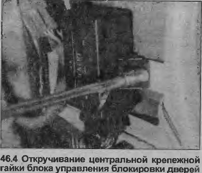
4. Unscrew the two mounting nuts and lift the block (see illustration).
5. Press the retaining clip to release the wiring connector, then remove the unit.
Installation
6. Installation is carried out in reverse order.
Control switch
Removal
7. The control switch is in the form of a micro switch, which is located inside the door at the rear of the outer handle assembly.
8. Remove the door trim panel as described in Section 11.
9. Pull back the plastic insulation sheet enough to access the outer handle.
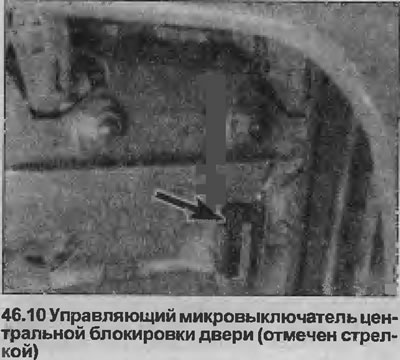
10. Unclip the microswitch from the rear edge of the outside handle assembly and disconnect the switch wiring connector from the door wiring harness, then remove the switch (see illustration).
Installation
11 Installation is carried out in reverse order.
Door lock control motor
Removal
12. Remove the door lock as described in Section 11.
13. Disconnect the lock lever transmission rod from the motor.
14. Unscrew the two mounting screws and remove the motor from the lock assembly.
Installation
15. Installation is carried out in reverse order.
Rear liftgate/trunk lid lock control motor
Removal
16. On Hatchback models, remove the screws securing and the rear liftgate trim panel.
17. Loosen the two mounting screws and pull the motor to disconnect the lock lever linkage.
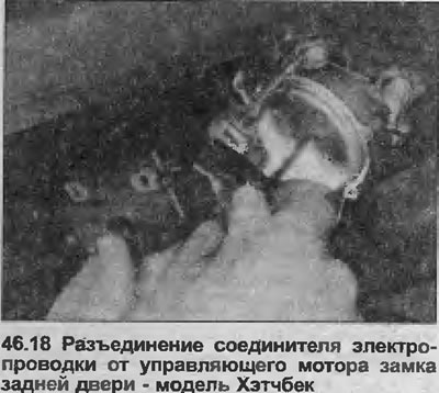
18. Remove the motor and disconnect the wiring connector (see illustration).
Installation
19. Installation is carried out in reverse order.
Fuel tank filler flap lock control motor
Removal
20. Remove the right rear luggage compartment trim panel as described in Section 11.
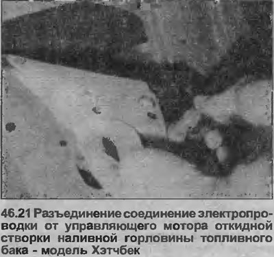
21. Disconnect the electrical connector at the rear of the motor (see illustration).
Article posted on an online resource: OPELBOOK
22. Remove the two screws securing the motor to the mounting bracket, then move the motor to disengage the lock linkage rod. Remove the motor.
Installation
23. Installation is carried out in reverse order.
Visitor comments