


Contents: Removal ⬇ Installation ⬇
When retracting the protective cover, the axle shaft does not need to be removed. You only need to remove the small clamp and lift the cover with a screwdriver, thereby letting air under it. Then secure the cover with a new clamp.
At a mileage of about 80,000 km, the axle shafts should be replaced as a set.
On the right axle shaft on some vehicle variants there are weights. When installing them, make sure to maintain the proper distance from them to the cover.
Removal
Engage any gear, apply the parking brake. Remove the cotter pin and unscrew the crown nut securing the hub.
[Text was copied from the portal: opelbook.ru]
Attention! The car must be on the ground, otherwise it may fall!
Loosen the front wheel mounting bolts.
Raise the front of the car.
Remove the front wheel, having first marked its position relative to the hub.
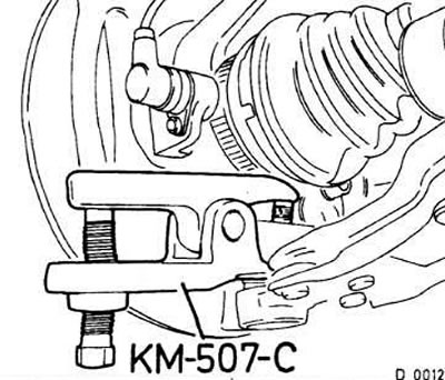
Unscrew the crown nut and press out the support using a regular puller or the Opel KM-507-S device (see fig.D0012).
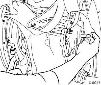
Knock out the axle shaft from the hinge housing. In workshops, a special device and a 1.5 kg hammer are used for this.
Attention! The front side of the device must face the gearbox.
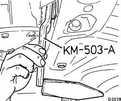
In vehicles with F-10/F-13 gearboxes (1.4/1.6 liter engines): knock the half-shafts out of the gearbox housing on both sides manually, using the KM-460-2-A device.
In vehicles with F-16 gearbox (1.8/2.0 l engines): knock out the left half-shaft using the KM-503-A device, and the right one using the KM-460-A device. In all-wheel drive vehicles, knock out the left half-shaft using the KM-503-A device, and the right one using a drift.
When removing the axle shaft, oil leaks out, so the hole in the gearbox must be closed with a suitable plug (for example, Opel ET N9092869).
If there are no special tools or the axle shaft is jammed, knock it out with a flat punch, after removing the cover from the differential.
Caution! Oil will leak out. Insert a flat punch between the end of the axle shaft and the bevel gear shaft and knock out the axle shaft.
Tie the axle shaft to the wire.
Remove the axle shaft from the wheel hub.
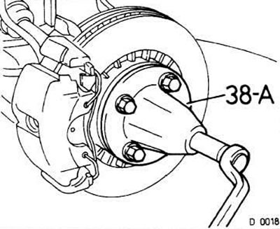
Caution! After removing the axle shaft, do not load the front wheel or move the vehicle, as this will disturb the installation of the thrust ball bearing. If you still need to move the vehicle, be sure to insert the axle shaft tail into the hub and tighten the crown nut.
For all work requiring removal of the axle shaft from the gearbox housing, force should be applied only to the axle shaft joint, not to the axle shaft itself. When removing the axle shaft from the hub, the same rule should be followed for the inner joint.
Installation
Caution! Handle the new axle shaft with care. It should not lie on the protective covers for a long time.
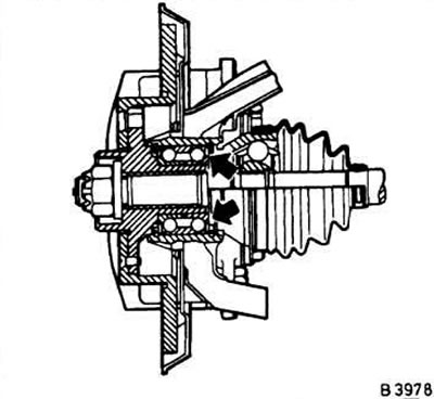
The mating surfaces of the outer joint and the axle shaft at the front hub ball bearing must be absolutely clean.
Lubricate the splines and bearing surfaces with oil.
Insert the axle shaft into the hub splines. Put on a new washer and castle nut and tighten the latter.
Lubricate the axle shaft installation location in the differential housing with oil.
Press the axle shaft into the differential housing by hand, then use a screwdriver to drive the retaining ring in until it snaps into place. To do this, place the screwdriver against the weld edge, but not against the lining.
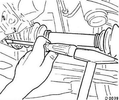
After the locking ring has snapped into place, check the tightness of the joint by pulling it by hand.
If the differential cover has been removed, install it with a new gasket, gluing the latter to the cover with bearing grease. Tighten the bolts to 30 Nm.
Add oil to the gearbox.
Insert the tip into the steering knuckle and tighten the castle nut to 70 Nm. Insert and bend the new cotter pin.
Install the front wheel, observing the previously applied markings.
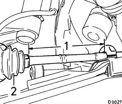
Set at distance 1 (equal to 267 mm) from the tide of the fastening of the cover of the outer hinge 2 compensation weight.
Lower the car.
Tighten the wheel bolts crosswise to 110 Nm.
Tighten the hub mounting nut to 130 Nm. Then loosen the nut and tighten it to 20 Nm. In this position, tighten the nut another ¼ turn.
Insert a new cotter pin and bend it; loosen the crown nut (and not to tighten) to the nearest hole.
Visitor comments