


Contents: Removal ⬇ Installation ⬇
Removal and installation are described separately depending on the engine type.
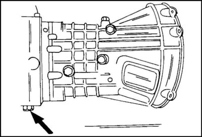
Drain plug for MSG gearbox. The plug is used to drain oil from the gearbox and transfer case.
Removal
Before removing the gearbox, it is necessary to carry out some preparatory work, described below. It is necessary to remove the gear shift and selection levers, as well as the shift linkage.
1. Raise and place the vehicle on stands.
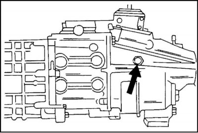
2. Remove the drain plug from the crankcase.
3. Drain the oil into a container provided.
4. Unscrew the four bolts.
5. Remove the shield under the transfer case.
6. For vehicles manufactured before 1997, disconnect the speedometer drive flexible shaft.
7. For vehicles manufactured after 1997, disconnect the plug connection of the speedometer drive. The exception is cars with ABS.
8. Disconnect the wires from the reverse light switch and the engine control switch.
9. Disconnect the wire from the all-wheel drive indicator lamp.
(Text copied from this portal: www.OpelBook.ru)
10. Remove the front and rear propeller shafts as described in the appropriate section.
11. Unscrew both bolts securing the clutch drive hydraulic working cylinder.
12. Remove the cylinder. Put it aside.
13. Place a garage lift under the gearbox (if necessary, place a wooden block underneath).
14. Raise the gearbox to relieve the load on the crossmember.
15. Loosen the bolts.
16. Remove the muffler mounting clamp from the crossmember.
17. Loosen the nuts securing the gearbox bracket in the center of the crossmember.
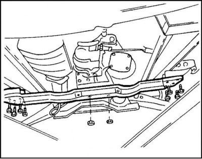
18. Unscrew the four bolts on the left and right sides of the crossbar where it is attached to the longitudinal beam. The cross member attachment to the gearbox is shown in the illustration.
19. Remove the connecting bolts between the engine and gearbox.
20. Carefully separate the engine from the gearbox. Be careful not to let the transmission fall off the jack. To do this, you need to use the help of an assistant. Keep in mind that the gearbox is very heavy.
Installation
The gearbox is installed as follows:
1. Thoroughly clean the mating surfaces of the gearbox and engine.
2. Also check that the clutch release bearing, input shaft spline and cover bushing are thoroughly cleaned.
3. If there is any doubt about the serviceability of the bearing, it must be replaced. The same applies to the clutch if it had operating defects before removal.
4. Lubricate all sliding and rotating surfaces with general purpose grease.
5. Engage the gear to facilitate engagement with the driven clutch disc.
6. Raise the gearbox with a garage jack and move it towards the engine.
7. Insert the gearbox input shaft into the clutch driven disc.
8. If the connection cannot be achieved immediately, it is necessary to turn the shaft flange back and forth several times until the shaft engages.
9. Press the gearbox fully against the engine. In this case, the two pins on the cylinder block must enter the corresponding holes in the gearbox.
10. Once the clearance between the engine and gearbox flanges has been selected, screw in the mounting bolts and tighten evenly to a torque of 70 Nm for engines up to mid-1995.
11. For later engines there are two sizes of bolts: large, tighten to 68 Nm, and small, tighten to 41 Nm. Leave the garage jack under the gearbox.
12. Install the cross member and secure.
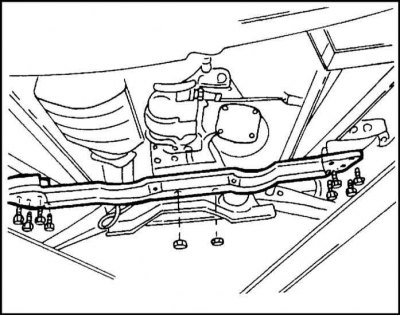
13. Tighten the bolts in the middle to 48 Nm, the bolts on the outside to 80 Nm.
14. Lower the garage lift and roll it out.
15. Screw in the clutch cylinder mounting bolts.
16. Tighten to 28 Nm.
17. Perform other work in the reverse order of removal.
18. Installation of the cardan shaft is described in the relevant section.
19. The tightening torque of the transfer case shield is 47 Nm.
20. Finally, fill the gearbox with oil.
21. Install the shift and selector levers as described below. The same applies to the shift linkage.
Visitor comments