


Control unit
1. Remove the panel at the bottom of the dashboard.
2. Release the 4 retaining clips and remove the cover from the heater core housing.
4. Note the position of the heater control rods in their clamps. If necessary, mark the rods and then disconnect them from the heater housing and from the damper actuator levers in the air distributor housing (see figure 2.10).
5. Unscrew the 2 self-tapping screws securing the heater control unit and remove it (see figure 2.11).
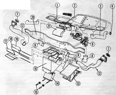
Figure 2.5. Heating system structure: 1. "Dashboard" gaskets; 2. Fresh air channel; 3. Side air nozzle channels (removing fog from window glass); 4. Side air nozzles (removing fog from window glass); 5. Blower motor; 6. Control unit; 7. Heater side vents; 8. Windshield defogger hose; 9. Control rod (air distribution valve); 10. Control rod (air mixing system); 11. Control rod (top control valve); 12. Heater ventilation hose; 13. Heater core casing; 14. Heater core; 15. Supply and return hoses of the cooling system; 16. Air distributor housing; 17. Upper air distribution valve; 18. Air mixing system damper; 19. Lower air distribution valve; 20. Engine compartment partition; 21. Central air duct.
6. Installation of the control unit is carried out in the reverse order. The control rods must be connected in the following sequence:
- a. Short rod - to the upper air distribution valve lever
- b. Intermediate rod - to the upper air distribution valve lever
- c. Long rod - to the air mixing system damper.
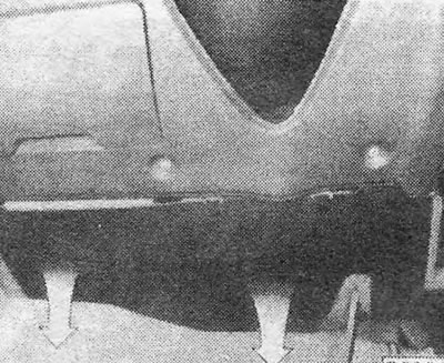
Figure 2.6. Removing the dashboard to gain access to the heater control unit
Blower motor
7. Open and support the hood.
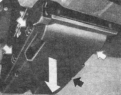
Figure 2.7. Removing the lower cover of the heater core - the cover retaining clips are shown by arrows
8. Remove the water deflector shield (if any) from the hole in the upper part of the engine compartment bulkhead (see figure 2.12).
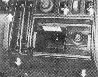
Figure 2.8. Removing the switch panel (clamps and screws are shown by arrows) - left-hand drive model
9. Disconnect the multi-pole plug of the blower motor (see photo).
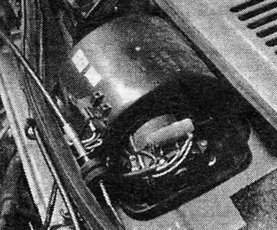
Photo 15.9. Heater blower motor.
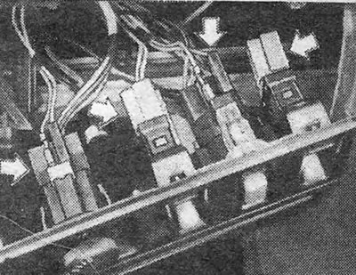
Figure 2.9. Electrical plugs of switches (shown by arrows)
10. Release the clamps securing the cover over the engine and remove it.
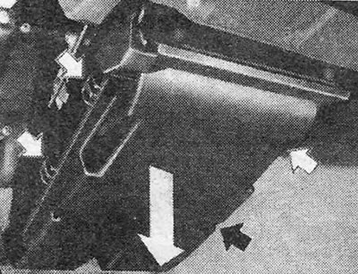
Figure 2.10. Control rods and levers (shown by arrows)
11. Remove the 2 screws securing the engine and remove it.
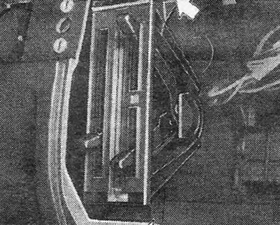
Figure 2.11. Screws securing the heater control unit (shown by arrows)
12. The engine is installed in the reverse order.
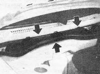
Figure 2.12. Removing the water deflector shield (the mounting clamps and screws are shown by arrows)
Heater core
13. Clamp the heater hoses at the rear bulkhead of the engine compartment.
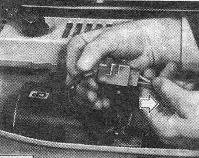
Figure 2.12. Removing the water deflector shield (the mounting clamps and screws are shown by arrows)
14. Disconnect the hoses from the heater core pipes.
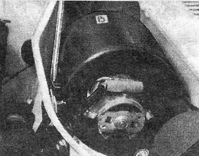
Figure 2.14. Removing the clamps securing the cover over the blower motor
15. Plug open pipes to prevent coolant from spilling when removing the core.
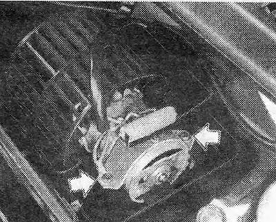
Figure 2.15. Blower motor mounting screws (shown by arrows)
16. Unscrew 2 screws and remove the center console.
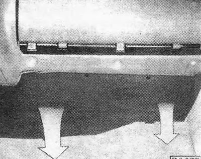
Figure 2.16. Removing the lower right panel "torpedoes" (shown by arrows)
(Original posted on the website: www.OPELBOOK.ru)
17. Remove the lower left and then the lower right dashboard panel (see chapter 11).
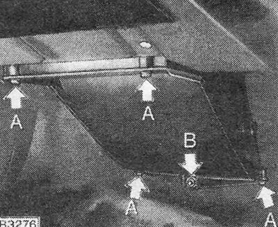
Figure 2.17. Fastening the heater core casing to the air distribution chamber
18. Release the 4 clamps and remove the cover at the base of the heater core housing (see photo).
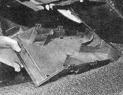
Photo 15.18. Heater blower motor cover.
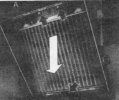
Figure 2.18. Core mounting screws visible with the damper (A) in the vertical position
19. Remove the 4 screws and 1 nut that hold the air distribution chamber flanges together (see figure 2.17).
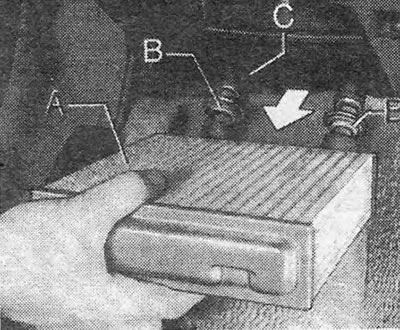
Figure 2.19. Removing the heater core: A. Serdtsevina; B. Rubber bushing; S. Partition.
20. Disconnect the air mixing system flap control rod.
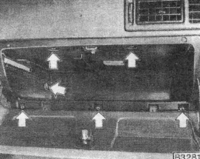
Figure 2.20. Screws securing the "glove compartment" (shown by arrows)
21. Disconnect the rod on the right side.
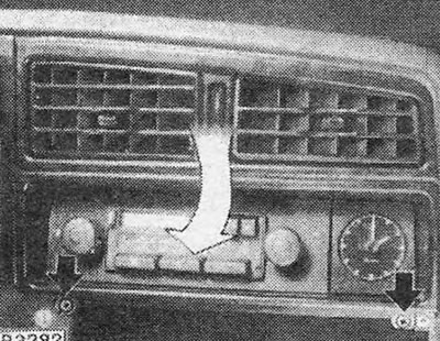
Figure 2.21. Removing the housing of the central fresh air vent (the mounting screws are shown by arrows)
22. Loosen the screws securing the core and remove it from the heater casing. To access the upper screws, move the flap (A) to a vertical position (see figure 2.18). As the core is removed, pull the pipes and their sealing bushings through the bulkhead (be prepared for some coolant to spill).
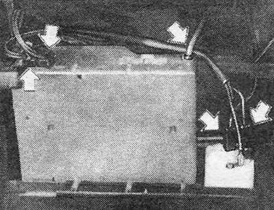
Figure 2.22. Electrical plugs for radio and clock (shown by arrows)
23. If the core is clogged, you should try backwashing (as for a radiator - see section 4). If this doesn't help, try adding radiator cleaner to the water (used strictly in accordance with the manufacturer's instructions).
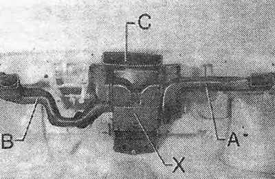
Figure 2.23. Air distributor housing with ventilation ducts: A. Heater side vent channel; B. Heater side vent channel; C. Central vent (for windshield); X. Air distributor housing.
24. If the core is leaking, it should be repaired by a specialist or replaced with a new one. Do not attempt to repair it yourself.
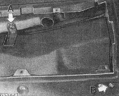
Figure 2.24. Screws (A) and (B) securing the instrument panel
25. The core is installed in the reverse order.
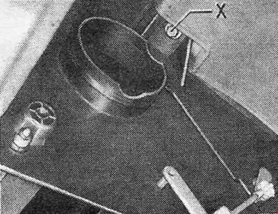
Figure 2.25. One of the screws (X) securing the air distributor housing to the bulkhead
26. Fill the system with coolant. On 1.3 engines, bleed the cooling system (see section 6).
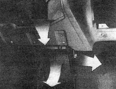
Figure 2.26. Removing the air distributor housing
Air distributor housing
27. Remove the heater core (see paragraphs 13-22).
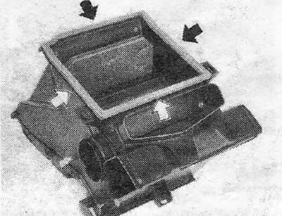
Figure 2.27. Sealing strip of the air distributor housing flange (shown by arrows)
28. Unscrew the screws and remove the "glove compartment" (see figure 2.20).
29. Remove the screws securing the switch panel. Pull the panel out, disconnect the plugs from the switches and remove the panel.
30. Loosen the 2 mounting screws and remove the heater lever assembly.
31. Remove the 2 screws securing the housing of the central fresh air supply vent, pull the housing down and out and remove it from the dashboard.
32. Disconnect the wiring from the radio and clock (if any) (see figure 2.22).
33. Disconnect the heater side vent channels and hose from the air distributor housing (X) (see figure 2.23).
35. Disconnect the air distributor housing at the top from the bulkhead and at the bottom - from the "torpedoes" panel (see figure 2.25).
36. Remove the air distributor housing (see figure 2.26).
37. Installation of the air distributor housing is carried out in the reverse order. Check the condition of the foam sealing strip (see figure 2.27) and connect the control rods (see paragraph 6).
Visitor comments