
Coolant pump (1.6,1.8 and 2.0 l, since 1987) - removal and installation
1. Loosen the tension on the camshaft timing belt as described in Section 3, paragraphs 9 to 18.
2. Remove the timing belt from the coolant pump chain ring, then remove the three pump mounting bolts.
3. Remove the pump from its place (see photo 4.3), and remove the O-ring if it remains on the cylinder block.
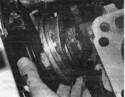
Photo 4.3 Removing the cooler pump
4. If you intend to replace the pump, you will need to remove the timing belt intermediate cover from the old pump and transfer it to the new pump. To do this, press the cover on the side while rotating it relative to the pump casing. The cover should at this time become detached from the casing flange as it turns (see photo 4.4). Install the cover on the new pump in the same way.
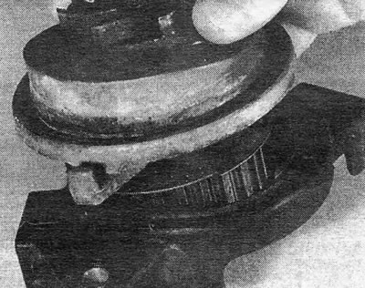
Photo 4.4 Removing the intermediate toothed belt cover from the cooler pump
5. Thoroughly clean the pump installation location on the cylinder block, as well as the pump itself if you are installing one that was previously installed.
6. Apply a generous amount of silicone grease to the friction surfaces of the pump housing and cylinder block, then install a new O-ring gasket on the pump.
7. Reinstall the pump and tighten its mounting bolts at this stage using only hand force.
8. Install and tension the camshaft timing belt as described in Section 3, paragraphs 21 to 29.
Thermostat housing (1.6, 1.8 and 2.0 l, since 1987) - removal and installation
9. The processes for removing and installing the thermostat remained unchanged for later models, however, if you want to remove and then install the thermostat, you will need to remove the camshaft timing belt and its rear cover to gain access.
10. To do this, follow the steps described in Section 3, paragraphs 30 to 36. Then you can unscrew the thermostat housing mounting bolts and remove the thermostat and spacer ring.
11. Using a new gasket, install the thermostat, and then carry out the operations described in Section 3, paragraphs 40 to 44.
Electric radiator cooling fan - modifications
1.2 On later models, the radiator fan shroud was modified and the method of attaching the radiator was changed.
13. The casing is now secured with two bolts at the top, and two protrusions at the bottom (see photo 4.13 A and B). Once the top bolts are removed, simply lift the entire assembly up to free the tabs.
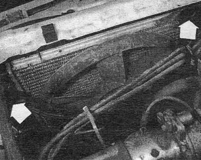
Photo 4.13 A Mounting bolts (indicated by arrows) cooler fan of a later type...
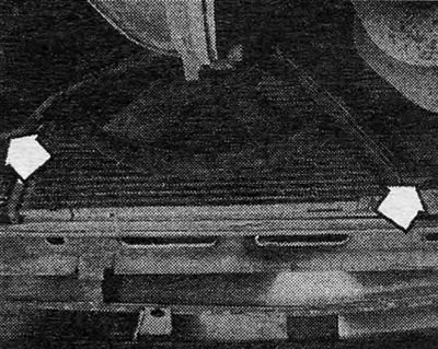
Photo 4.13 B... and lower mounting lugs (indicated by arrows
14. Apart from this, all other processes are carried out in the same way as described in Chapter 2.
Visitor comments