
Removing
Before removing the anti-roll bar, the engine must be secured on the left side of the engine bracket in such a way that the engine is held on the raised vehicle from the ground and that there is sufficient clearance to lower the front subframe.
Engage the handbrake and jack up the front of the vehicle and secure it to jack stands under the bridge.
On dual cam models, remove the lower mudguard as directed in chapter 11.
If desired, for better access to parts, remove the front section of the exhaust system, as indicated in chapter 4.
Working under the vehicle, loosen and remove the nuts securing the anti-roll bar to the lower control arms. Remove the concave washers and rubber pads.
Make sure the engine is secured, then remove the two nuts and washers securing the transmission/engine assembly to the subframe.
Support the subframe with a wheel jack, placing wooden blocks.
Unscrew the two rear and two central bolts securing the subframe to the bottom of the car body. Note that the rear bolts also secure the lower arms to the subframe. These bolts are very tight.
Note. Some older models used a short front frame that was secured with four bolts instead of six. On these models, remove all four subframe bolts and then remove the subframe from the vehicle.
Loosen, but do not remove, the two bolts securing the front subframe to the underbody (does not apply to some older models).
Carefully lower the subframe until the subframe and anti-roll bar bolts are accessible. then unscrew the bolts.
Remove the anti-roll bar from the subframe.
Installation
If desired, the anti-roll bar locating bushings can be replaced as indicated in the next section.
Installation is carried out in the reverse order of removal, taking into account the following.
During installation of the subframe, new rear bolts must be installed and tightened in three stages, as indicated in the specification.
Connect the ends of the anti-roll bar to the lower arms, making sure that the concave washers holding the rubber pads are installed with the concave side towards the lower arm.
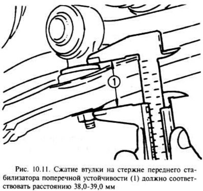
Install new nuts securing the anti-roll bar to the lower arm and tighten them so that the rubber bushing is compressed, as shown in Fig. 10.11. If necessary, replace rubber bushings.
Install new anti-roll bar lock nuts and torque to specification.
Tighten all nuts and bolts to specification.
If necessary, install the front section of the exhaust system (see chapter 4).
Visitor comments