


Contents: Removal the cylinder head cover ⬇ Removal the cylinder head cover ⬇ Dismantling the camshaft ⬇ Dismantling camshafts ⬇
Cylinder head work – starting with dismantling – requires a more in-depth knowledge of the subject than was necessary in the description of previous repair and maintenance work. In addition, a torque wrench is now required as an essential tool.
Removal the cylinder head cover
8-valve engine
The cylinder head cover - often also called the valve cover - is removed from our engines as follows:
- Unscrew the cable channel from the valve cover and set it aside.
- Remove the engine ventilation hose clamp from the pipe with pliers and remove the hose. Also remove the thin hose from the cylinder head cover.
- Remove the cylinder head cover mounting bolts.
- Carefully remove the cylinder head cover from the camshaft housing so as not to damage the gasket.
- Replace the damaged gasket.
- When installing, tighten the fastening bolts starting from the middle of the cover, crosswise to 8 Nm.
Removal the cylinder head cover
16V
- 16V 1.6L Engine: Disconnect Battery Ground Cable
- Disconnect all wire connectors in the upper intake manifold area.
- Remove the cable channel from the clamps and set it aside.
- Remove the secondary air changeover valve vacuum hose.
- Unscrew the brake booster vacuum line on the top of the intake manifold.
- Disconnect the vacuum hose on the top of the intake manifold that goes to the intake manifold pressure sensor.
- Slide the fuel tank vent valve up from the bracket and set it aside.
- Remove the fuel tank vent valve vacuum hose and fuel pressure regulator hose from the top of the intake manifold.
- Unscrew the fastening clamp of the connecting pipe.
- Remove the mounting bolts on the lower part of the intake manifold and on the cylinder head cover.
- Remove the upper portion of the intake manifold from the cylinder head cover.
- 16V engine with a displacement of 1.8 and 2.0 l: unscrew the ignition cable cover
- Disconnect the wire connector from the camshaft position sensor.
- For all engines: Disconnect the spark plug connectors and remove them from the mounts.
- Remove the clamps and crankcase ventilation hoses from the cylinder head cover.
- Unscrew the cylinder head cover from the cylinder head and carefully lift it up.
- Carefully remove the cylinder head cover - pay attention to the sealing rings!
- Remove any remaining gasket and clean the sealing surfaces.
- Install the cylinder head cover with new sealing rings and new gaskets. Lubricate the gaskets with sealant.
- When installing, install the sealing rings with a small amount of Vaseline in the cylinder head cover so that they do not fall into the cylinder head when installing the cover.
- When installing, tighten the fastening bolts, starting from the middle of the cover, crosswise (8 Nm).
Dismantling the camshaft
8-valve engine
- Remove the front timing belt cover.
- It is impossible to dismantle the camshaft with the cylinder head installed using home remedies, because the valves must be compressed with clamps when performing this work. Valve clamps are sold in specialized stores. A new camshaft seal is also required.
- Remove the cable channel on the cylinder head
- Remove the engine ventilation hose and unscrew the cylinder head cover.
- Turn the crankshaft to the ignition timing position of cylinder 1 and then back ¼ turn. This will put all the pistons in the middle position and the camshaft will not press on the pendulum arms.
- Loosen the timing belt and remove it from the camshaft pulley. To do this, turn the tension roller, counteracting the spring force, upward until the holes on the tension roller align. Fix the tension roller in this position with a suitable pin or drill.
- Unscrew the camshaft pulley. At the same time, press the camshaft with an open-end wrench in the opposite direction using the Allen key provided for this purpose
- Remove the battery support, see chapter on battery.
- Remove the DIS ignition module (chapter "Ignition").
- Remove the carrier plate underneath. Replace the carrier plate sealing ring, clean the sealing surface.
- Unscrew the printed circuit board from the cylinder head.
- Cover the oil recirculation holes to prevent the stops from falling inward during installation.
- Press the valves down evenly with the clamps
- Remove the camshaft from the housing.
- Remove the old camshaft sealing ring by screwing a self-tapping screw into the sealing ring and pulling it out with pliers.
- If a new camshaft is installed, the pendulum arms must be replaced.
- When installing, lubricate the sliding surfaces of the camshaft, stops and pendulum levers with MoS ₂ grease. Do not frighten the parts
- Lightly lubricate the new shaft seal and use a suitable pin to drive it into the camshaft housing.
- Before installing the camshaft, check that the crankshaft is at 60 BTDC.
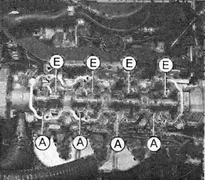
The photograph shows the location of the intake (E) and exhaust (A) valves in the cylinder head of an 8-valve engine.
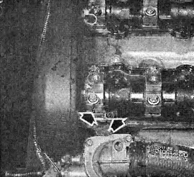
Removing the camshaft bearing caps in a 16V engine: the arrows show where the numbers are on the bearing caps and on the cylinder head. Removing the bearing caps is only done in a specific sequence, see text below.
- When applying the timing belt, be sure to observe the valve timing.
- Tightening torques: printed circuit board on camshaft housing - 8 Nm, carrier plate on camshaft housing - 8 Nm (use a new gasket). Camshaft pulley - 45 Nm.
- After installing the camshaft, the engine can only be started after 30 minutes, see. advice on the next page.
Dismantling camshafts
16V
- Turn the engine to 60° until the 1st cylinder ignites.
- Loosen and remove the timing belt.
- Remove the cylinder head cover.
- Unscrew the camshaft pulleys. To do this, press the corresponding camshaft with an open-end wrench by the hexagon in front of the first cam.
- First loosen bearing caps 1, 3 and 5 (intake camshaft), respectively 6, 8 and 10 (exhaust camshaft) half a turn and then one turn.
- Now alternately loosen bearing caps 2 and 4 in a criss-cross pattern (intake camshaft), respectively, 7 and 9 (exhaust camshaft) and remove them. The camshaft should be released evenly from the bearing seats.
- When installing, lubricate the sliding surfaces of the valve tappets and camshafts with MoS2 paste. Apply sealant (90350544) to the sealing surfaces of the outer camshaft bearing caps (1 and 6).
- Install the camshafts so that both locking pins on the end faces of the camshafts are facing upwards. In 16V engines with a working volume of 1.8 and 2.0 liters, the pins should be turned slightly outward towards the intake manifold, respectively, towards the exhaust manifold.
- Place the bearing caps so that the same code numbers are opposite each other on the cap and the bearing seat.
- Screw the bearing caps of the corresponding camshaft from the inside out. Tighten the nuts step by step to 8 Nm.
- Lubricate the new camshaft seals and install using a suitable drift.
- Screw on the camshaft pulleys with new bolts (50 Nm + 60° + 15P). Mount the camshaft pulley with cylinder identification hoods on the exhaust camshaft. The valve timing markings must point forward.
- For 16V 1.8L and 2.0L engines, install the camshaft pulleys so that the intake camshaft guide pin fits into the "IN" hole in its pulley. And the exhaust camshaft guide pin fits into the "EX" hole in its pulley.
- Put on the toothed belt. Check the valve timing.
- Tighten the timing belt and check the tension.
- After installing the camshafts, the engine can only be started after 30 minutes, see. advice on the next page.
Visitor comments