


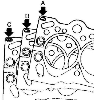
A – no hole – 1.4 mm
B - one hole - 1.45 mm
C – two holes – 1.5 mm
Removal
1. Drain the coolant from the cooling system.
2. Remove the intake and exhaust manifolds.
3. Remove the camshaft pulley.
4. Unscrew the bolts securing the rear timing belt cover to the cylinder head.
5. Loosen the clamps and disconnect the coolant supply hoses to the thermostat housing and cylinder head.
6. Unscrew the nuts and remove the wires from the glow plugs.
7. Disconnect the connector from the coolant temperature sensor.
8. Disconnect the fuel supply lines from the fuel injectors and high pressure fuel pump and remove the lines.
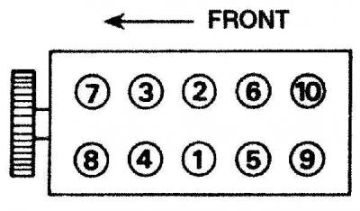
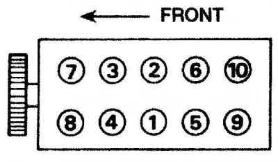
9. Gradually loosen the cylinder head mounting bolts in the reverse order to that shown in the figure.
10. Remove the bolts together with the washers.
11. Remove the head from the cylinder block and the gasket.
Preparing for installation
1. The mating surfaces of the engine head and cylinder block must be thoroughly cleaned of gasket residue and carbon deposits using a plastic or wooden scraper. It is also necessary to clean the upper parts of the pistons. When cleaning, eliminate the possibility of cleaning products getting into the oil channels of the cooling system. Thoroughly clean the inner surfaces of the cylinders.
2. Check the mating surfaces of the engine head and cylinder block for defects. Minor damage can be repaired by mechanical treatment. Also, using a metal ruler and feeler gauge, check the flatness of the mating surfaces.
3. Clean the bolt holes in the block. Driving a bolt into an oil filled hole can cause the block to burst due to hydraulic pressure.
4. Depending on the amount of piston protrusion from the cylinder block, it is necessary to use a head gasket of a strictly defined thickness. The thickness of the gasket is identified by holes punched in the left front corner of the gasket (see Fig. Hole locations for cylinder head gasket thickness identification).
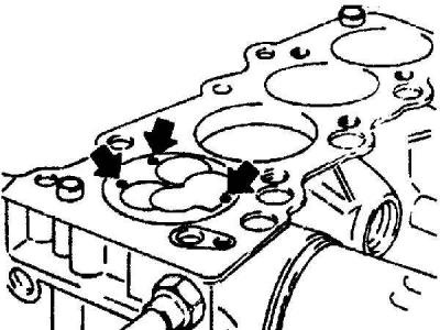
5. Check that the crankshaft is at the top dead center of the piston of the first cylinder. Mount a dial indicator on a bracket on the cylinder block. Mount the measuring tip on the cylinder block and set the dial indicator scale to 0. Mount the measuring tip on the piston of the first cylinder and slightly turn the crankshaft in both directions and mark the highest value on the indicator. Record this value. Check the piston protrusion at three points (the points are indicated by arrows).
6. Measure the piston protrusion on cylinder N4 in the same way. Then turn the camshaft 180° and repeat the piston protrusion measurement on cylinders 2 and 3. Turn the camshaft 540° and reset it to its original position.
7. Determine the average piston projection by adding the 12 piston projection measurements and dividing the total by 12. Use the average piston projection measurement to select a cylinder head gasket (see table).
|
Piston protrusion
|
Gasket thickness
|
|
0.58 – 0.64 mm
|
1.40 mm
|
|
0.65 – 0.70 mm
|
1.45 mm
|
|
0.71 – 0.78 mm
|
1.50 mm
|
Installation
Warning: When installing the cylinder head, new bolts must be used.
1. Wipe the mating surfaces of the cylinder block and cylinder head.
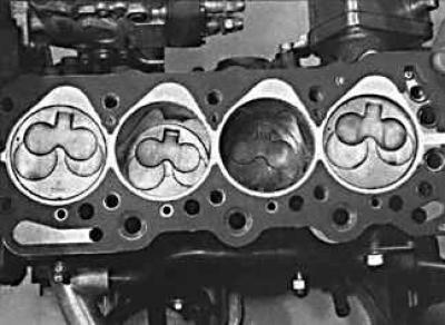
2. Check that the two guide pins are installed in the cylinder head and install the cylinder head gasket.
3. Check that the crankshaft pulley mark is aligned with the pointer and that the camshaft is installed in the cylinder head so that the cams of the first cylinder are facing upward.
4. Install the cylinder head.
5. Lubricate the cylinder head bolts with engine oil and carefully insert them into the sockets. Tighten the head bolts by hand.
(Text copied from this portal opelbook.ru)
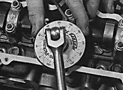
6. Tighten the cylinder head bolts in several stages in the sequence shown in the figure.
7. Further installation is carried out in the reverse order of removal. Fill the cooling system with coolant.
Visitor comments