


Contents: Checking the rotor ⬇ Stator check ⬇ Checking the brushes ⬇ Checking bearings ⬇ Checking the rectifier unit ⬇ Checking the voltage regulator ⬇
Check the generator components for wear or damage and replace if necessary.
Checking the rotor
Check the rotor slip rings for dirt and roughness. If there is any roughness, sand it with fine-grained sandpaper.
Use a caliper to measure the diameter of the slip rings. If the diameter is less than the minimum allowable, replace the rotor.
Slip ring diameter:
- nominal: 14.4 mm
- minimum acceptable: 12.8 mm
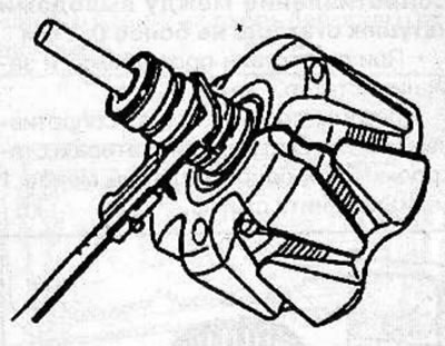
Use an ohmmeter to measure the resistance between the contact rings. If the resistance is less than 2.9 ohms, there is a short circuit in the rotor winding. If there is no conductivity, then there is a break in the rotor winding, and the rotor must be replaced.
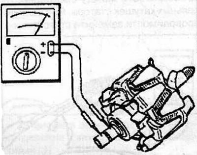
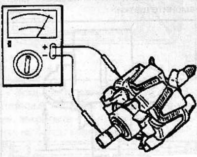
Use an ohmmeter to check the conductivity between the slip ring and the rotor armature. If there is continuity, replace the rotor.
Stator check
Use an ohmmeter to check for conductivity between the terminals of each stator coil.
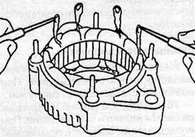
Resistance between stator coil terminals: no more than 0.1 Ohm
If there is no conductivity, replace the stator.
Use a megohmmeter to check the resistance between the stator coils and the stator. If the resistance is less than 1 mOhm, replace the stator.
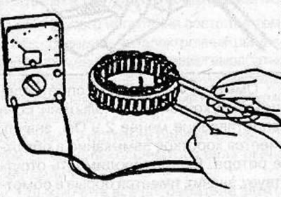
Use an ohmmeter to check for conductivity between the terminals of individual stator coils. If there is continuity, replace the stator.
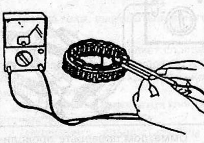
Checking the brushes
Check the length of the brushes. If the brush length is equal to or less than the specified length, replace the brushes.
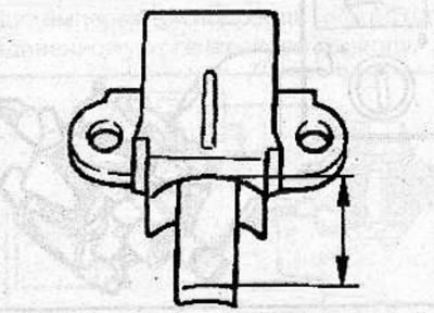
Length of brushes:
- nominal: 10 mm
- minimum acceptable: 8.4mm
Warning: Replace both brushes at the same time.
Checking bearings
Make sure the front bearing rotates smoothly and without binding. Replace the bearing if necessary.
Make sure the rear bearing rotates smoothly and without binding. Replace the bearing if necessary.
Checking the rectifier unit
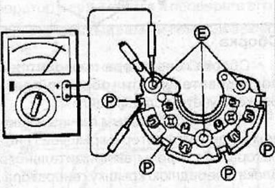
Use a tester to check the conductivity between terminals P and E as shown in the figure. Make sure that when you connect one probe to terminal P and the second to terminal E, there is conductivity; when connected in reverse, there is no conductivity. If there is continuity in both cases, replace the rectifier unit.
Checking the voltage regulator
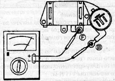
Use a tester to check the conductivity between terminals B and F as shown in the figure. Make sure that when you connect one probe to terminal B and the second to terminal F, there is conductivity; when connected in reverse, there is no conductivity. If there is continuity in both cases, replace the voltage regulator.
Visitor comments