
OpelBook.ru
Cars AvtoVAZ Cars Mitsubishi Cars BMW Cars Mercedes Cars Nissan Cars Toyota Cars Chevrolet
English Русский
Български
Беларускі
Український
Српски
Hrvatski
Română
Polski
Slovenský
Magyar
 |  Sitemap  |  Contacts  |    


Main Astra Corsa Insignia Kadett Omega Vectra Zafira Others Articles
Frontera A (1991-1998, petrol) Frontera B (1998-2004) Ascona C (1981-1988) Vivaro A (2001-2014)
  • Main
  • Opel
  • Frontera A
  • Chassis
  • Rear suspension
  • Removal and installation of the axle housing (flat spring suspension)

Removal and installation of the axle housing (flat spring suspension) (Opel Frontera A)

            0

Contents: Removal ⬇ Installation ⬇
In the description below, a distinction should be made between vehicles with flat leaf spring suspension and vehicles with coil spring suspension. First you need to find out what type of car you have.

Raise the rear of the vehicle and place it on stands. Loosen the mounting bolts and remove both wheels.

Removal


1. Unscrew the cap of the brake fluid reservoir, cover the hole with polyethylene and close the cap again. This way, it is possible to prevent the bulk of the fluid from leaking out when opening the brake system.
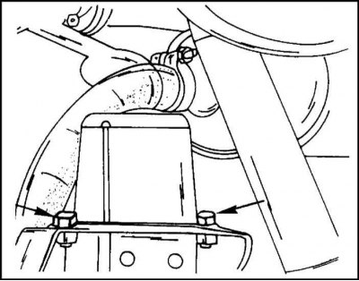
2. Unscrew the two bolts securing the buffer to the bracket on the chassis, shown by the arrows,…


2. Unscrew the two bolts securing the buffer to the bracket on the chassis, shown by the arrows, and remove the buffer.

3. Loosen the nuts on the end of the parking brake equalizer to disengage the ends of the cables from the equalizer.

4. Disconnect both cables.
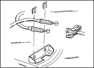
5. Remove the locking plates from the bracket on the chassis and remove the cables downwards. The…


5. Remove the locking plates from the bracket on the chassis and remove the cables downwards. The fastening of the cables to the equalizer is shown in the illustration.


6. Disconnect the brake pressure regulator connecting rods from the rear axle. To do this, remove the cotter pin from the connection and unscrew the crown nut.

7. Do not remove the bracket from the bridge.

8. Loosen the union nut connecting the brake hose to the brake pipeline and remove the pipeline.

9. Seal the end of the pipeline to prevent dirt from entering (for example, with adhesive tape).

10. Now the brake hose can be disconnected from the elbow.

11. Remove the lock plate using a mandrel and pliers.
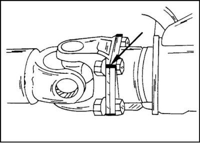
12. Mark both propeller shaft joint flanges with paint as shown and remove the four bolts and nuts…


12. Mark both propeller shaft joint flanges with paint as shown and remove the four bolts and nuts (let the paint dry first).

13. Disconnect the propeller shaft from the axle flange, supporting the shaft so that it does not fall. You can secure the shaft to the chassis with wire or put something underneath.

14. Place a garage lift under the bridge and raise the bridge until the shock absorbers are compressed.

15. Disconnect the lower shock absorber mounts from the support pins on the U-bolt pads.
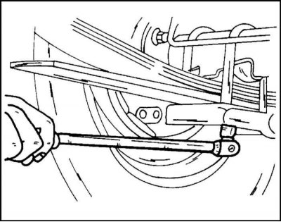
16. Unscrew the nuts securing the stirrups from the bottom side of the bridge.


16. Unscrew the nuts securing the stirrups from the bottom side of the bridge.


17. Remove the washers and carefully knock the stirrups upwards. To avoid skewing the ladder, strike evenly on the right and left. Be careful not to damage the threads.

18. Separate the rear axle from the chassis with the help of an assistant. Make sure that the parking brake cables do not become entangled.

19. Lower the bridge onto the lift.

Installation


When installing the bridge, keep the following in mind:

Check the condition of the stepladders. The ladders "spread" after they are removed. Therefore, it is necessary to check whether the ladder rods fit into the holes on the bridge. If not, then one rod of the stepladder is clamped in a vice, and the second one is carefully bent.

It may happen that when installing a new axle, it will be necessary to move the brake hose and pipe, as well as the parking brake cables from the old axle.

1. Place the bridge on the chassis and connect it to the springs.

2. Check that the spring center bolt fits into the corresponding holes in the axle.

3. Insert step ladders on top.
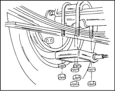
4. Install and bolt the step ladder pads from below. The shock absorber support pin on the…


4. Install and bolt the step ladder pads from below. The shock absorber support pin on the stepladder should face inward as shown.


5. Screw on four nuts and tighten them evenly in a criss-cross pattern.
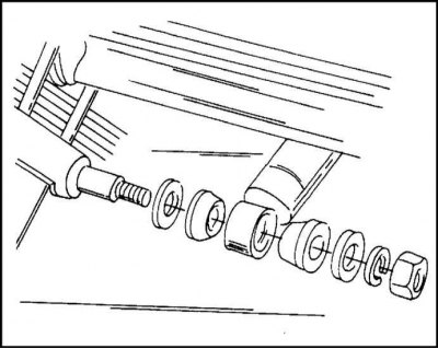
6. Secure the shock absorber from below. The location of the fastening parts is shown in the…


6. Secure the shock absorber from below. The location of the fastening parts is shown in the illustration.

7. Don't forget to install the spring washer.

8. Tighten the nuts to a torque of 40 Nm.

9. Set the buffer.

10. Tighten the mounting bolts to a torque of 42 Nm.

11. Secure the bridge ventilation hose.

12. Connect the flanges of the cardan shaft and the main gear pinion in accordance with the marking and insert new bolts. Old bolts are not installed.

13. Tighten the nuts to a torque of 75 Nm.

14. Install the brake pressure regulator connecting rods using the washer and spring washer.

15. Tighten the castle nut by hand.

16. Don't pin it yet.

17. Attach the brake hose to the elbow and install the spring clamp. Make sure the hose is positioned correctly.

18. Screw on and tighten the brake line union nut.
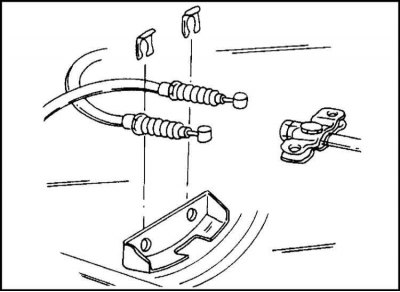
19. Secure the parking brake cables as illustrated to the locking plates on the chassis.


19. Secure the parking brake cables as illustrated to the locking plates on the chassis.


20. Lower the vehicle onto its wheels and tighten the U-bolt mounting nuts evenly and crosswise to a torque of 68 Nm.

21. Tighten the brake pressure regulator rod castellated nut to 13 Nm and secure with a cotter pin.

22. Finally, bleed the brake system as described in Chapter 9.

23. Remove the plug from the bridge and check the oil level. Add oil if necessary. If the oil has been drained from the bridge, it must be refilled.

The source is on the online website www.opelbook.ru


This article is available at russian, bulgarian, belarusian, ukrainian, serbian, croatian, romanian, polish, slovak, hungarian
Checking the article: Meshcheryakov Damir

Share information:

Previous articles
Opel Frontera A: Rear suspension
Next articles

Rear wheel suspension and rear axle — general information
Removal and installation of the axle housing (suspension with coil springs)
Removal and installation a coil spring
Removal and installation the shock absorber
Removal and installation the trailing arm
Removal and installation the middle arm
Removal and installation the transverse reaction rod and rubber bushings


See similar ones from other Opel car manuals:
▶ Rear Suspension Coil Spring — Removal and Installation Opel Astra F (1991-1998, petrol)
▶ Removal and installation the rear suspension spring (Corsa… Opel Corsa B (1993-2000)
▶ GNC Rear Suspension Spring Replacement Opel Insignia A (2008-2017)
▶ Rear suspension coil spring (single overhead camshaft… Opel Vectra A (1988-1995, petrol)
▶ Front suspension Opel Kadett E (1984-1995)
Link to this page in different formats

Visitor comments


No comments yet


How much will 16 + 45 =


Vivaro A (2001-2014) 
  • General information
  • User manual
  • Power unit
  • Petrol engine F4R
  • Diesel engine F9Q
  • Diesel engine G9U
  • Transmission
  • Clutch and drive shafts
  • Manual gearbox
  • Chassis
  • Front suspension
  • Rear suspension
  • Brake system
  • Body
  • Exterior
  • Interior
  • Electrical equipment
  • Heating and ventilation
  • Air conditioner
  • Equipment and devices
  • Electrical diagrams
Ascona C (1981-1988) 
  • General information
  • Maintenance
  • Power unit
  • Gasoline engines
  • Diesel engines
  • Cooling system
  • Fuel and exhaust system
  • Contact ignition system
  • Contactless ignition system
  • Transmission
  • Clutch
  • Mechanical gearbox
  • Automatic gearbox
  • Drive shafts
  • Chassis
  • Steering
  • Brake system
  • Car suspension
  • Body
  • Exterior
  • Interior
  • Doors and windows
  • Electrical equipment
  • Equipment and devices
  • Power devices
  • Electrical circuits
Frontera B (1998-2004) 
  • General information
  • User manual
  • Maintenance
  • Power unit
  • Petrol engines 2.2 l
  • Petrol engines 3.2 l
  • Diesel engines 2.2 l
  • Cooling system
  • Fuel system (petrol)
  • Fuel system (diesel)
  • Ignition system
  • Transmission
  • Clutch
  • Manual gearbox MUA5C
  • Automatic gearbox 4L30E
  • Chassis
  • Suspension and axles
  • Steering
  • Brake system
  • Body
  • Exterior
  • Interior
  • Doors, locks and windows
  • Heating and air conditioning
  • Electrical equipment
  • Power devices
  • Equipment and devices
  • Lighting and signaling
  • Electrical diagrams
Frontera A (1991-1998, petrol) 
  • General information
  • Introduction to guide
  • User manual
  • Maintenance
  • Power unit
  • Engine repair
  • Lubrication system
  • Cooling system
  • Power and exhaust system
  • Engine electrics
  • Transmission
  • Clutch
  • Mechanical gearbox
  • Cardan shafts
  • Chassis
  • Brake system
  • Front suspension
  • Rear suspension
  • Steering
  • Body
  • Repair and care
  • Electrical equipment
  • Equipment and devices
  • Electrical circuits
OpelBook.ru © 2017–2026 · Mobile version · · Sitemap: EN BG BY UA RS HR RO PL SK HU · Feedback · Site search
Astra F, petrol · Astra G, petrol · Astra G · Astra H · Astra J, petrol · Corsa B · Corsa C, petrol · Corsa C · Insignia A · Kadett D · Kadett E · Omega A · Omega B · Omega B2 · Vectra A, petrol · Vectra A · Vectra B, petrol · Vectra B · Vectra C · Zafira A, petrol · Frontera A, petrol · Frontera B · Ascona C · Vivaro A ·
We want your visit to be comfortable 🤝! We use cookies 🍪 to make that happen.