
OpelBook.ru
Cars AvtoVAZ Cars Mitsubishi Cars BMW Cars Mercedes Cars Nissan Cars Toyota Cars Chevrolet
English Русский
Български
Беларускі
Український
Српски
Hrvatski
Română
Polski
Slovenský
Magyar
 |  Sitemap  |  Contacts  |    


Main Astra Corsa Insignia Kadett Omega Vectra Zafira Others Articles
Frontera A (1991-1998, petrol) Frontera B (1998-2004) Ascona C (1981-1988) Vivaro A (2001-2014)
  • Main
  • Opel
  • Frontera A
  • Chassis
  • Rear suspension
  • Removal and installation of the axle housing (suspension with coil springs)

Removal and installation of the axle housing (suspension with coil springs) (Opel Frontera A)

            0

Contents: Removal ⬇ Installation ⬇

Removal


1. Unscrew the brake fluid reservoir cap, cover the hole with polyethylene and screw the cap back on. This prevents the bulk of the oil from leaking out of the brake system.

2. Place a lift under the center of the rear axle and raise the axle slightly.

3. Loosen the nuts on the end of the parking brake equalizer to disengage the ends of the cables from the equalizer.

4. Disconnect both cables.

5. Remove the locking plates from the bracket on the chassis and remove the cables downwards.
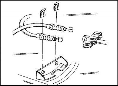
6. The attachment of the cables to the equalizer of a vehicle with leaf springs is shown in the…


6. The attachment of the cables to the equalizer of a vehicle with leaf springs is shown in the illustration. This mount looks exactly the same on a three-door car. The five-door car has a similar mount.

7. Disconnect the parking brake cables from the bracket on the chassis. Fastening is carried out by four locking plates with bolts.

8. Loosen the union nut connecting the brake hose to the brake pipeline and remove the pipeline.

9. Seal the end of the pipeline to prevent dirt from entering (for example, with adhesive tape).

10. Now the brake hose can be disconnected from the elbow.


11. Remove the lock plate using a mandrel and pliers.
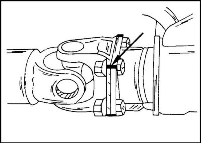
12. Mark both propeller shaft joint flanges with paint as shown and remove the four bolts and nuts…


12. Mark both propeller shaft joint flanges with paint as shown and remove the four bolts and nuts (let the paint dry first).

13. Disconnect the propeller shaft from the flange of the main gear drive of the axle, supporting the shaft so that it does not fall. You can secure the shaft to the chassis with wire or put something underneath.
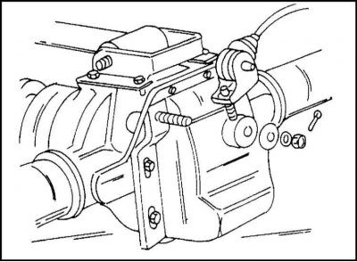
14. Disconnect the brake pressure regulator connecting rods from the bracket on the rear axle. The…


14. Disconnect the brake pressure regulator connecting rods from the bracket on the rear axle. The fastening is shown in the illustration.
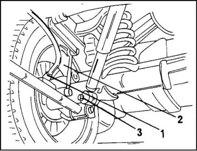
15. The following work is carried out in accordance with the illustration on both sides of the car.…


15. The following work is carried out in accordance with the illustration on both sides of the car. First, disconnect the parking brake cables by removing the locking plates (1). Unscrew the nuts securing the anti-roll bar connecting rods (2) and, after unscrewing the nut (3) and removing the washer from the journal, remove the shock absorber.


16. Disconnect the ventilation hose from the bridge.

17. Slowly lower the lift, releasing the shock absorbers.

18. Remove the springs and upper spring isolators.
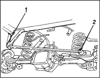
19. Remove the mounting nut from the support journal and remove the cross reaction rod shown in the…


19. Remove the mounting nut from the support journal and remove the cross reaction rod shown in the illustration.

20. Loosen the ABS speed sensor cable mounting bolt on the middle arm. The plug connection and cable are also secured to the chassis.
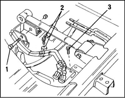
21. To disconnect, unscrew the bolt (3) shown in the illustration. Now the middle axle arm can be…


21. To disconnect, unscrew the bolt (3) shown in the illustration. Now the middle axle arm can be disconnected. To do this, unscrew the bolt (1) and nut.
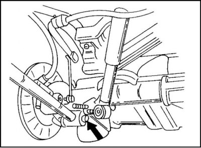
22. Disconnect the trailing arm from the bridge. To do this, unscrew the two bolts and nuts on each…


22. Disconnect the trailing arm from the bridge. To do this, unscrew the two bolts and nuts on each side of the car. Carefully knock out the bolts. Since the bridge is no longer secured, it must be secured on the lift with the help of an assistant.


23. Carefully roll the bridge out from under the vehicle on the lift.

Installation


The bridge is installed in the reverse order of removal. In this case, it is necessary to keep the following in mind:

It may happen that when installing a new axle, it will be necessary to move the brake hoses and pipes, as well as the parking brake cables from the old axle.

Mounting elements with a rubber coating must not be exposed to lubricants. Lubricants should also not be kept near the above mentioned areas.

1. First tighten the bolts and nuts securing all mounting elements that have a rubber coating by hand.

2. After lowering the vehicle onto its wheels, tighten the specified connections to the specified torques.

3. Place the rear axle on a lift under the car (the bridge must be held in place) and stop it near the ends of the longitudinal arms.
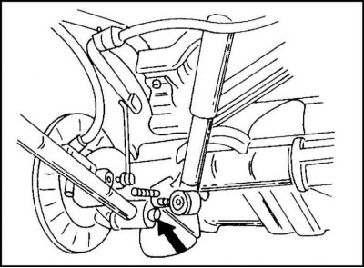
4. Connect both trailing arms at the locations shown in the illustration.


4. Connect both trailing arms at the locations shown in the illustration.

5. As stated above, tighten only by hand. The trailing arms must move.
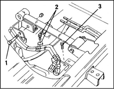
6. Reinstall the middle lever as shown in the illustration.


6. Reinstall the middle lever as shown in the illustration.


7. Secure the ABS cable to the lever and tighten the ABS connector bracket bolt to 26 Nm.

8. Do not tighten the bolt and nut securing the middle arm yet.
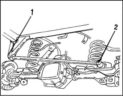
9. Install the cross reaction rod as shown in the illustration. There should be a washer under the…


9. Install the cross reaction rod as shown in the illustration. There should be a washer under the nut. Do not tighten the nut yet.
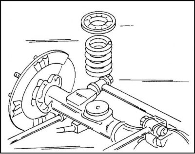
10. Install the coil springs with the upper isolating pads onto the axle.


10. Install the coil springs with the upper isolating pads onto the axle.

11. Slowly raise the bridge, making sure the springs are positioned correctly at the top and bottom.

12. Now lift the bridge so that the springs are compressed.

13. Install the shock absorber on the bridge. The nut (3) is screwed on with a washer. The connecting rods (2) are secured to the bridge with nuts. The parking brake cables are secured to the trailing arm with clamps (1) and bolts (9 Nm).
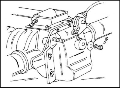


14. Connect the brake pressure regulator rods to the bridge.


14. Connect the brake pressure regulator rods to the bridge.

15. Fix the brake hose to the corner, insert the brake pipe and fix it.

16. Secure the parking brake cables to the chassis brackets.

17. Tighten all bolts to 9 Nm.

18. Attach the parking brake cables to the equalizer and secure with staples to the bottom of the chassis.

19. Connect the flange of the cardan shaft to the flange of the main gear drive pinion in accordance with the marking.

20. Insert new bolts and tighten them to 75 Nm.

21. Install and secure the rear wheels.

22. Lower the car onto its wheels.

23. Now tighten the suspension fastening elements that have rubber parts to the following torques.

24. Finally, tighten the brake drum mounting bolts.

25. Bleed the brake system as described in Chapter 9.

26. Adjust the parking brake.

27. Check the oil level in the rear axle. Add oil if necessary.


This article is available at russian, bulgarian, belarusian, ukrainian, serbian, croatian, romanian, polish, slovak, hungarian
Checking the article: Meshcheryakov Damir

Share information:

Previous articles
Opel Frontera A: Rear suspension
Next articles

Removal and installation of the axle housing (flat spring suspension)
Rear wheel suspension and rear axle — general information
Removal and installation a coil spring
Removal and installation the shock absorber
Removal and installation the trailing arm
Removal and installation the middle arm
Removal and installation the transverse reaction rod and rubber bushings
Removal and installation the anti-roll bar


See similar ones from other Opel car manuals:
▶ Removal and installation rear suspension coil springs Opel Astra H (2004-2009)
▶ Removal and installation rear suspension coil springs Opel Corsa C (2000-2006)
▶ Removal and installation rear suspension coil springs Opel Vectra C (2002-2008)
▶ Removal and installation front suspension springs Opel Kadett E (1984-1995)
▶ Rear suspension springs — removal and installation Opel Omega B (1993-1999)
Link to this page in different formats

Visitor comments


No comments yet


How much will 35 + 34 =


Vivaro A (2001-2014) 
  • General information
  • User manual
  • Power unit
  • Petrol engine F4R
  • Diesel engine F9Q
  • Diesel engine G9U
  • Transmission
  • Clutch and drive shafts
  • Manual gearbox
  • Chassis
  • Front suspension
  • Rear suspension
  • Brake system
  • Body
  • Exterior
  • Interior
  • Electrical equipment
  • Heating and ventilation
  • Air conditioner
  • Equipment and devices
  • Electrical diagrams
Ascona C (1981-1988) 
  • General information
  • Maintenance
  • Power unit
  • Gasoline engines
  • Diesel engines
  • Cooling system
  • Fuel and exhaust system
  • Contact ignition system
  • Contactless ignition system
  • Transmission
  • Clutch
  • Mechanical gearbox
  • Automatic gearbox
  • Drive shafts
  • Chassis
  • Steering
  • Brake system
  • Car suspension
  • Body
  • Exterior
  • Interior
  • Doors and windows
  • Electrical equipment
  • Equipment and devices
  • Power devices
  • Electrical circuits
Frontera B (1998-2004) 
  • General information
  • User manual
  • Maintenance
  • Power unit
  • Petrol engines 2.2 l
  • Petrol engines 3.2 l
  • Diesel engines 2.2 l
  • Cooling system
  • Fuel system (petrol)
  • Fuel system (diesel)
  • Ignition system
  • Transmission
  • Clutch
  • Manual gearbox MUA5C
  • Automatic gearbox 4L30E
  • Chassis
  • Suspension and axles
  • Steering
  • Brake system
  • Body
  • Exterior
  • Interior
  • Doors, locks and windows
  • Heating and air conditioning
  • Electrical equipment
  • Power devices
  • Equipment and devices
  • Lighting and signaling
  • Electrical diagrams
Frontera A (1991-1998, petrol) 
  • General information
  • Introduction to guide
  • User manual
  • Maintenance
  • Power unit
  • Engine repair
  • Lubrication system
  • Cooling system
  • Power and exhaust system
  • Engine electrics
  • Transmission
  • Clutch
  • Mechanical gearbox
  • Cardan shafts
  • Chassis
  • Brake system
  • Front suspension
  • Rear suspension
  • Steering
  • Body
  • Repair and care
  • Electrical equipment
  • Equipment and devices
  • Electrical circuits
OpelBook.ru © 2017–2026 · Mobile version · · Sitemap: EN BG BY UA RS HR RO PL SK HU · Feedback · Site search
Astra F, petrol · Astra G, petrol · Astra G · Astra H · Astra J, petrol · Corsa B · Corsa C, petrol · Corsa C · Insignia A · Kadett D · Kadett E · Omega A · Omega B · Omega B2 · Vectra A, petrol · Vectra A · Vectra B, petrol · Vectra B · Vectra C · Zafira A, petrol · Frontera A, petrol · Frontera B · Ascona C · Vivaro A ·
We want your visit to be comfortable 🤝! We use cookies 🍪 to make that happen.