
Removing
1. Remove the power block from the engine compartment (see relevant chapter).
2. Disconnect the gearbox from the engine.
3. Remove the timing cover.
4. Remove the cylinder head (see relevant chapter).
5. Remove a cover of a back epiploon of a cranked shaft.
6. Remove the mounting bolts and remove the connecting rod bearing caps.
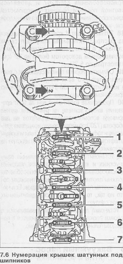
Attention! Bearing caps 1-5 are marked with the corresponding numbers on the side of the exhaust valves (see arrows in illustration). Caps 6 and 7 are not numbered.
7. Loosen the bolts of the main bearing caps, proceeding in sequence 1-7, unscrew the bolts and lay as follows. so that when assembling, install the covers in their original places 9cm. illustration). If available, use the KM-849 tool.
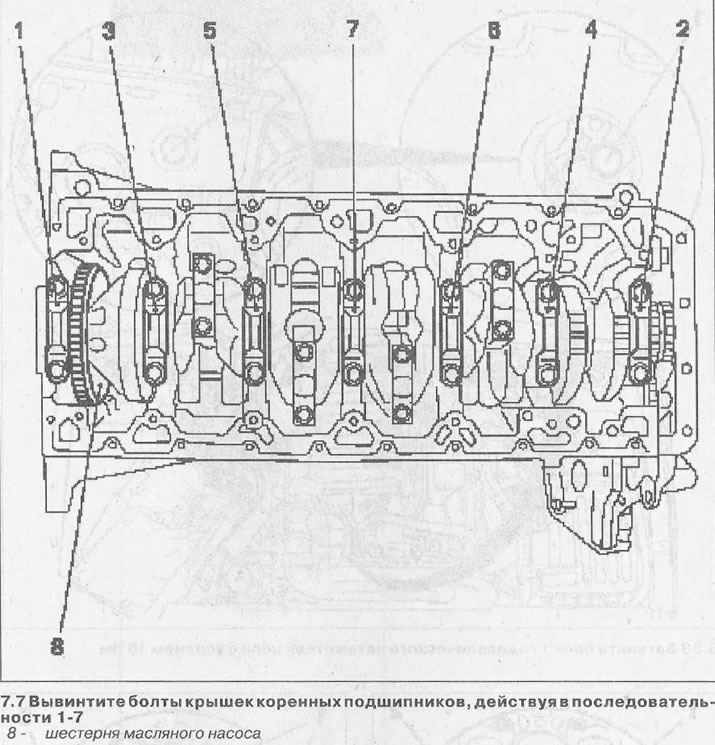
8. Remove the main bearing caps and lay them in a sequence that ensures their subsequent installation in their original mounting locations. If there are covers for laying, you can use the KM-849 fixture.
Attention! Do not place the removed crankshaft on the oil pump gear.
9. Take a cranked shaft from a flea of cylinders.
10. Clean and inspect all parts for damage and wear and replace if necessary.
Attention! In case of replacing the crankshaft, remove the oil pump gear from the old one and fix it on the new shaft by tightening the mounting bolts with a force of 5.5 Nm.
Installation
11. Grease loose leaves of radical bearings with engine oil and lay them in the block of cylinders.
12. Establish covers of radical bearings and fix them with new bolts. When suspending the covers, make sure that the recesses on them coincide with the lower recesses for the engine oil outlet (see arrows in illustration).
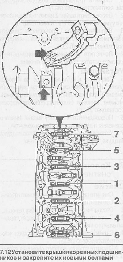
13. Tighten the bolts securing the main bearing caps with a force of 25 Nm and subsequent turning by 50°, proceeding in sequence 7-1 (see illustration 7.12).
14. Install connecting rod bearings.
15. Establish a cover of a back epiploon of a cranked shaft, having replaced a former sealing lining on new.
16. Install the timing cover.
17. Connect the gearbox to the engine and install the power unit in the engine compartment.
Crankshaft - checks
Clearance between the shells and the necks of the main bearings of the crankshaft. Measurement with calibrated plastic wire - method «Plastigage»
The gap between the liners and the necks of the main bearings of the crankshaft is checked by calculation by measuring the details. Before this, the crankshaft and its necks are cleaned, and the liners are lubricated with a thin layer of engine oil.
18. Usually, a calibrated plastic wire is used to check the gap.
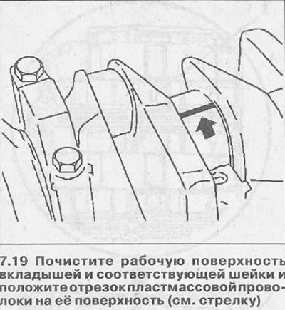
19. Clean the working surface of the earbuds and the corresponding neck and place a piece of plastic wire on its surface (see arrow in illustration).
20. Install the main bearing cap on the neck to be checked, and tighten the mounting bolts with a force of 25 Nm, followed by a 50°additional turn.
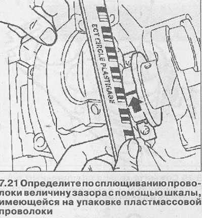
21. Unscrew the bolts and remove the bearing cover, and then, using the scale on the packaging of the plastic wire, determine the amount of clearance by flattening the wire (see illustration). The permissible gap between the liners and covers is 0.020-0.058 mm.
Measuring the clearance of connecting rod bearings with a caliper
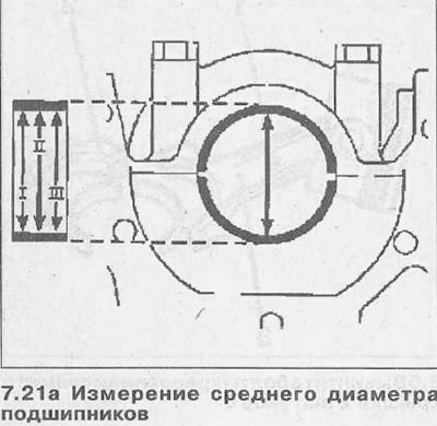
In this case, the clearance between the connecting rod bearing shells is determined by measuring the bearing diameter with a caliper at three points. The results obtained are summarized and divided by 3. As a result, the average value of the diameter is obtained (see illustration 7.21a).
Example:
I - the result obtained when measuring at point I - 57.972 mm
II - the result obtained when measuring at point II - 57.981 mm
III - the result obtained when measuring at point III - 57.984 mm
173.937: 3 = 57.979 mm
22. Measure the diameter of the respective connecting rod journal at two points with a micrometer, sum the values obtained and divide them by 2.
Example:
I - the result obtained when measuring at point I - 57.962 mm»
II - the result obtained when measuring at point II - 57.964 mm
115.926: 2= 57.963 mm
To obtain the clearance value of the connecting rod bearing shells, subtract the journal diameter value from the bearing diameter value:
57.979 mm - 57.963 mm = 0.016 mm
The allowable gap is 0.016-0.058 mm.
Visitor comments