
Removing
1. Remove the cylinder head (see relevant chapter).
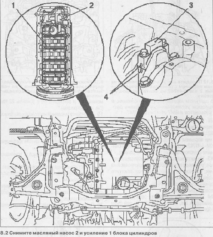
2. Remove oil pump 2 (see relevant chapter) and reinforcement of 1 cylinder block (see illustration).
3. Mark the mounting position of the pistons, caps and connecting rod bearing shells 3. Connecting rods 4 and their caps have the same marking (see illustration 8.2).
4. Remove carbon deposits from the top of the cylinders and remove the corresponding piston along with the connecting rod.
5. Unscrew bolts of fastening and remove covers 2 rods 3 (see illustration).
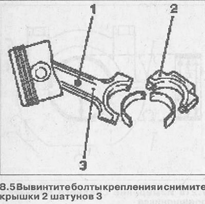
6. Lay the removed connecting rod caps together with the liners so that you can later install them in their original places.
Attention! According to color code 1, one red and one blue bushing must be installed in each bearing. Insert with marking «S» is the top liner.
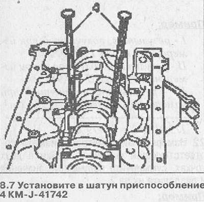
7. Install tool 4 KM-J-41742 into the connecting rod (see illustration).
8. Lubricate the pistons and their rings with a thin layer of engine oil.
9. Install the rings on the pistons, placing their locks 120°relative to each other.
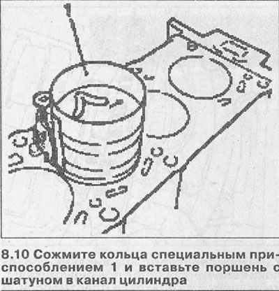
10. Compress the rings with a special tool 1 and insert the piston with the connecting rod into the cylinder bore. The arrow on the piston crown must point towards the timing gear (see illustration).
Attention! The corresponding connecting rod journal must, when installing the piston with the connecting rod, be in a position in which the installed piston is located at TDC or before TDC.
11. Tap the piston with a hammer handle until it is fully seated in the cylinder bore.
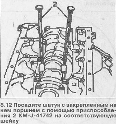
12. Place the connecting rod with the piston fixed on it using tool 2 KM-J-41742 on the corresponding neck and remove the tool (see illustration).
13. Lay the connecting rod bearing shells, guided by the color marking on them, install the connecting rod caps, screw in new bolts for their fastening and tighten them with a force of 20 Nm, followed by a 60°turn.
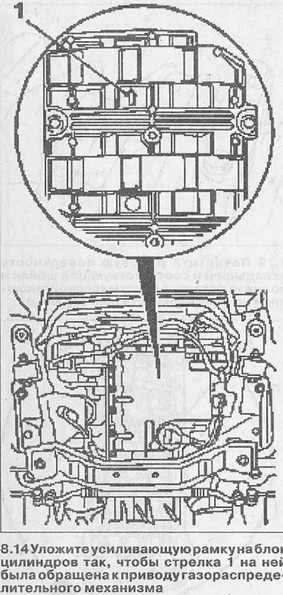
14. Lay the reinforcing frame on the cylinder block so that the arrow 1 on it faces the timing gear drive, and secure it with a force of 22 Nm (see illustration).
15. Install the oil pump and cylinder head.
Piston rings - removal and installation
16. Remove the piston from the cylinder bore along with the connecting rod.
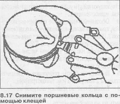
17. Remove piston rings with pliers (see illustration).
18. Clean the rings and their grooves on the piston. To clean the grooves, you can use the old ring.
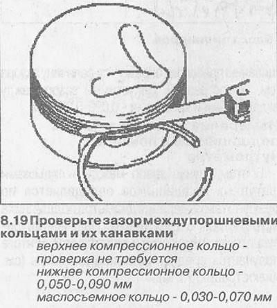
19. Check the gap between the piston rings and their grooves using feeler gauges (see illustration).
20. Check the clearance in the piston ring lock using feeler gauges by inserting the rings into the gauge (see illustration).
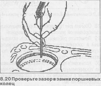
Permissible clearance in the piston ring lock:
- upper compression ring - 0.20-0.40 mm,
- lower compression ring - 0.40-0.65 mm,
- oil scraper ring - 0.25-0.45 mm.
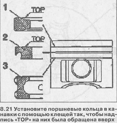
21. Install the piston rings in the grooves with pliers so that the inscription «TOR» facing them up (see illustration), and their locks were located at 120°relative to each other.
Piston - replacement
22. Remove the piston from the cylinder bore along with the connecting rod.
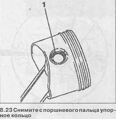
23. Remove thrust ring 1 from the piston pin using needle nose pliers or other suitable tool and press out the pin (see illustration). Attention! The piston and piston pin are matched to each other and their rearrangement is not allowed.
24. Before installing the piston, measure the calculated clearance between the piston and the cylinder by measuring the piston diameter with a micrometer at several points at a distance of 90°from each other, departing from its skirt by 7 mm (see illustration).
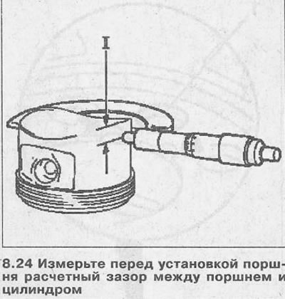
25. Measure the diameter of the cylinder bore using a caliper in three belts (see illustration).
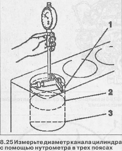
The gap between the piston and the cylinder for new engines is 0.031-0.063 mm, while for used engines it can reach 0.15 mm.
Measurement example:
- cylinder bore diameter - 80,000mm
- piston outer diameter - 79.955mm
- clearance 0.045 mm
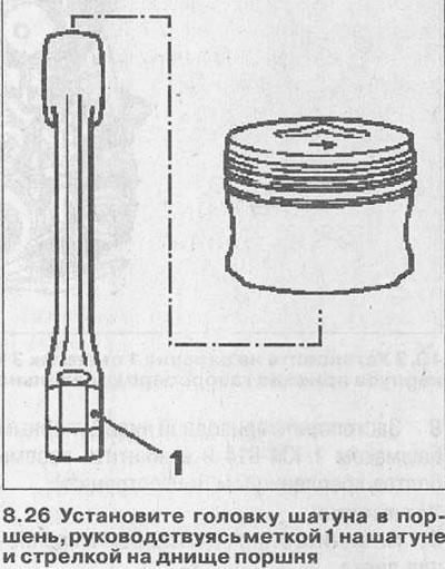
26. Install the connecting rod head into the piston, guided by mark 1 on the connecting rod and the arrow on the piston bottom, which should face the timing gear drive after the connecting rod and piston group is installed in the cylinder block (see illustration).
27. Lubricate the piston pin with engine oil and press it in by hand to the seating groove of the thrust ring.
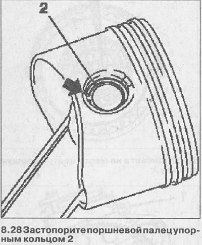
28. Lock the piston pin with the thrust ring 2. The ends of the ring must rest against the corresponding protrusion (see arrow in illustration).
Visitor comments