
Attention! The procedure for removing the engine from the engine compartment and its installation is given on the example of a car with a Y25DT engine and a manual transmission. Removal and installation of other types of engines are carried out similarly.
All wires and other removable parts when dismantling the engine should be laid and secured in the same way as they were located before they were disconnected.
Removing
1. Set the steering wheel to the straight ahead position, turn on the ignition, remove the key from the ignition and disconnect the wire terminal «masses» (-) from the negative pole of the battery.
2. Cars with air conditioning. Drain the coolant.
Attention! All work on the air conditioning system must be carried out by a specialist workshop to avoid injury.
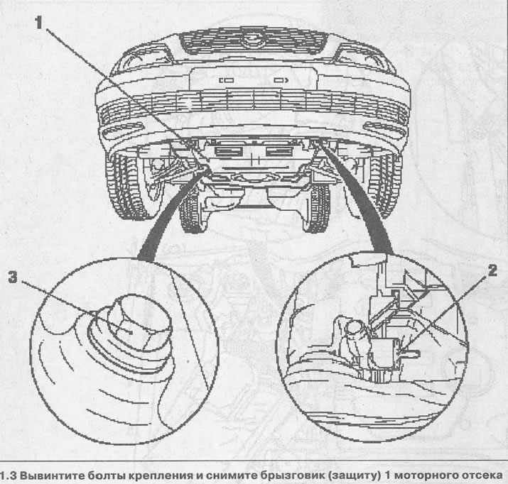
3. Unscrew the mounting bolts and remove the mudguard (protection) 1 engine compartment (see illustration).
4. Drain the coolant into a container by unscrewing drain plug 2 on the radiator and plug 3 on the cylinder block (see illustration 1.3).
5. Remove the radiator blower together with the viscous coupling.
6. Disconnect the supply air duct.
7. Disconnect the charge air hose from the turbocharger.
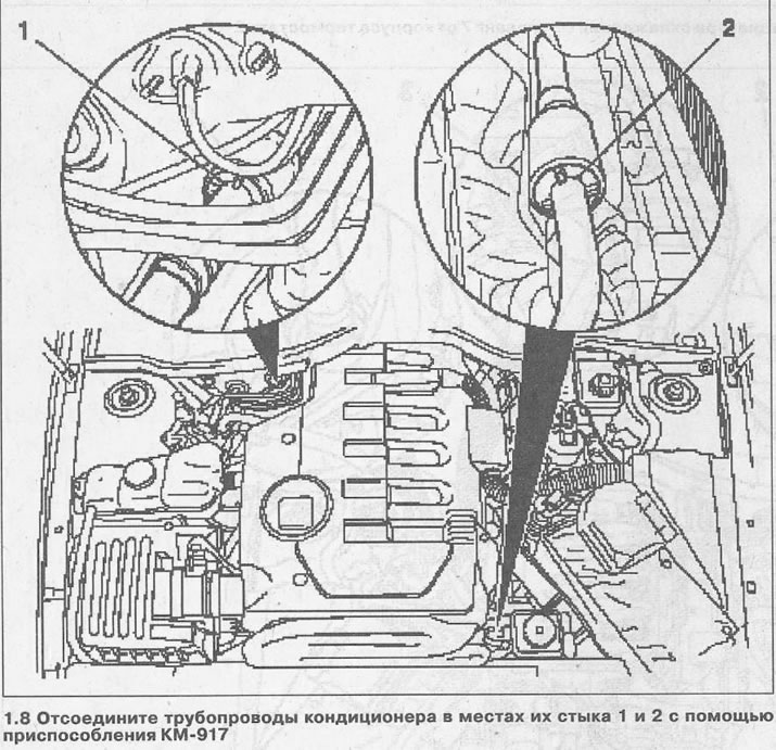
8. Disconnect the air conditioning pipelines at their junctions 1 and 2 using the KM-917 tool (see illustration).
9. Disconnect the cooling hose 3 from the radiator for cooling the exhaust gases returned for afterburning and the hose 7 from the thermostat housing 2 by disconnecting their quick-release fasteners (see illustration).
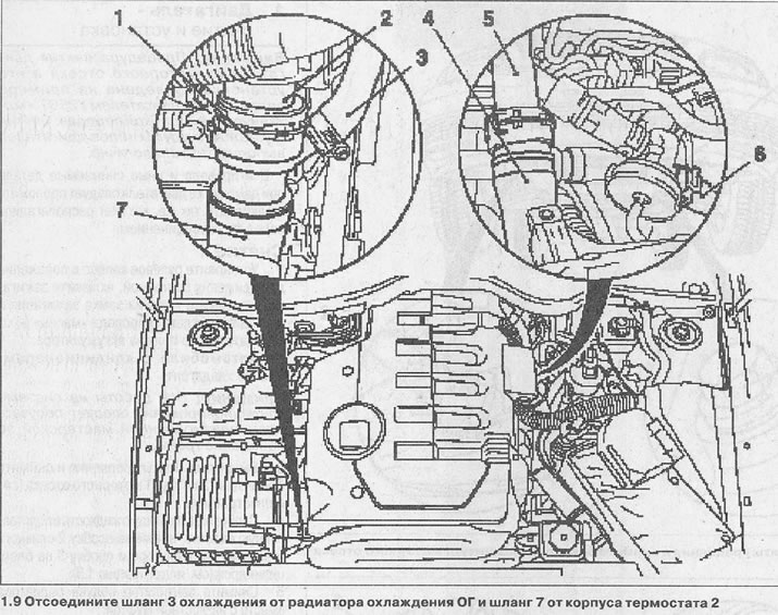
10. Disconnect the cooling hose 4 from the flange 5 on the cylinder block and put it aside (see illustration 1.8).
11. Disconnect the cooling hose 6 from the changeover valve heater (see illustration 1.8).
12. Disconnect hose 1 from pipeline 2 of the cooling system (see illustration).
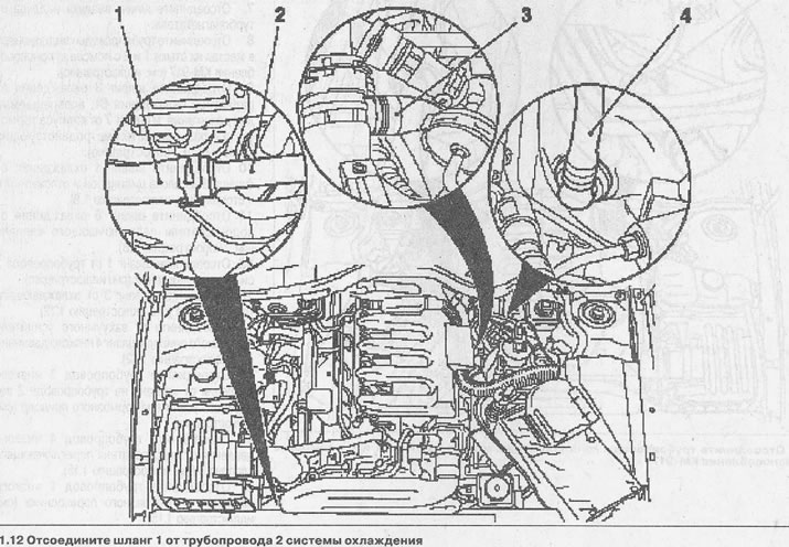
13. Disconnect hose 3 from the cooling pipeline (see illustration 1.12).
14. Disconnect low pressure hose 4 from the vacuum brake booster (see illustration 1.12).
15. Disconnect the low pressure line 3 from the valve on line 2 of the vacuum brake booster (see illustration).
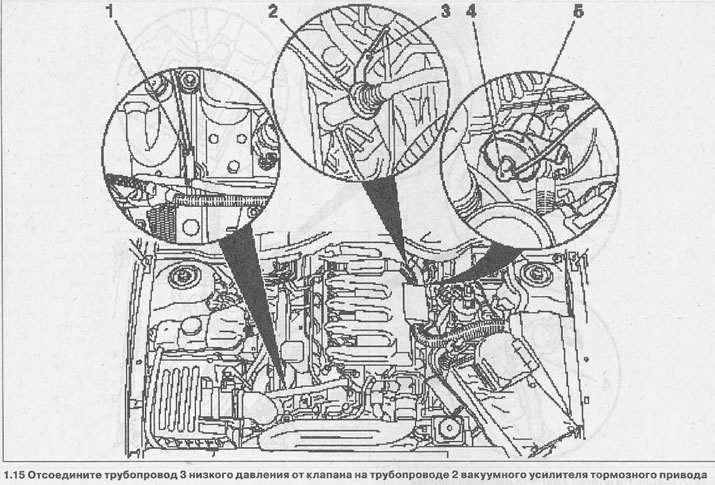
16. Disconnect low pressure line 4 from changeover valve heater 5 (see illustration 1.15).
17. Disconnect the low pressure line 1 from the T-piece (see illustration 1.15).
18. Remove the cover 7 from the relay block 8 by pressing the latches (see illustration).
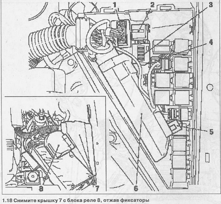
19. Disconnect plug 5 coolant temperature sensor (see illustration 1.18).
20. Remove the engine control unit 6 from the bracket of the relay unit and disconnect the plug 4 (see illustration 1.18).
21. Disconnect relays 3, 2 and relay 1 of the preheater (see illustration 1.18).
22. Disconnect the plug 2 fuel pressure sensor (see illustration).
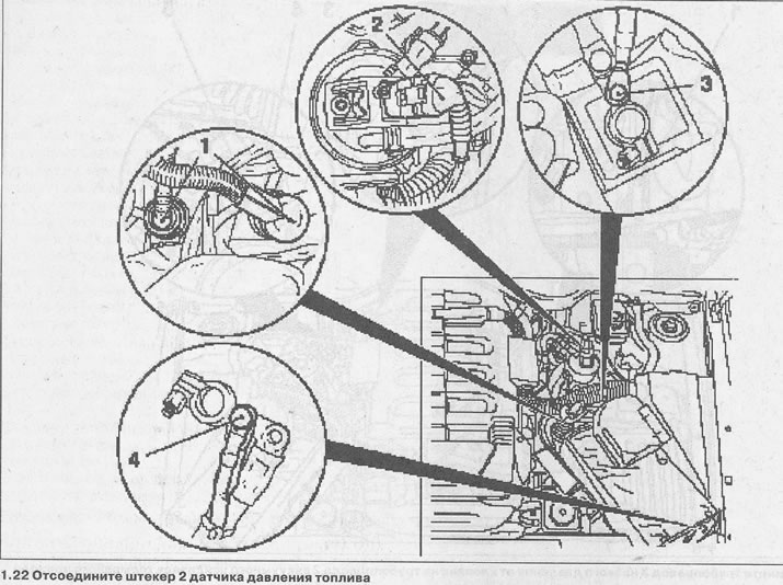
23. Disconnect the positive potential wire terminal from the battery, unscrew the fastening bolt and disconnect the additional wire 3 from the terminal (see illustration 1.22).
24. Unscrew the mounting bolt and disconnect from the wire terminal «masses» (-) additional wire 4 (see illustration 1.22).
25. Disconnect the multi-pin plug 1 and move the engine wiring harness to the side (see illustration 1.22).
26. Disconnect wire 3 from the positive potential wire terminal by unscrewing the fastening bolt (see illustration).
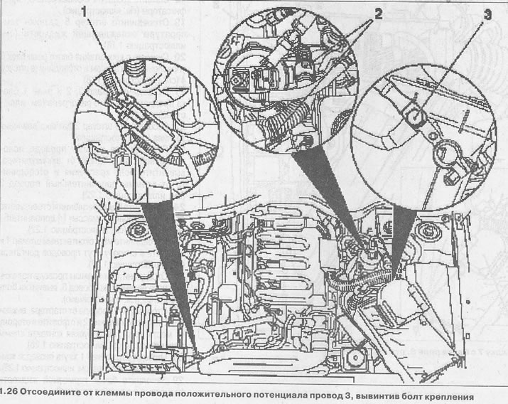
27. Disconnect the wires from the starter, release them from the fasteners 2 and put them aside from the place of work, avoiding contact between the terminals of these wires (see illustration 1.26).
28. Disconnect the plug 1 of the wiring harness of the air conditioning compressor (see illustration 1.26).
29. Fill the brake fluid reservoir completely and close the cap.
30. Loosen the clamp on the pipeline near the bulkhead of the engine compartment (see illustration).
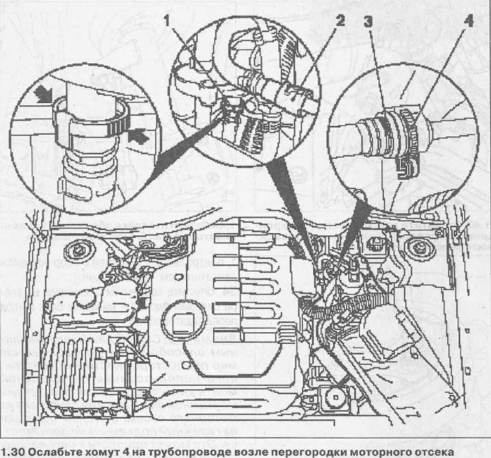
31. Pry with a small screwdriver and remove the locking bracket 3, and then disconnect the clutch actuator pipeline. Install the retaining clip after disconnecting the pipeline in place so that it is not lost (see illustration 1.30).
32. Disconnect the fuel supply line 2 using the KM-796-A tool (see illustration 1.30).
33. Disconnect the fuel return line 1 by pressing on the quick connector leashes (see arrows in illustration 1.30).
34. Take the fluid from the reservoir 1 of the power steering (see illustration).
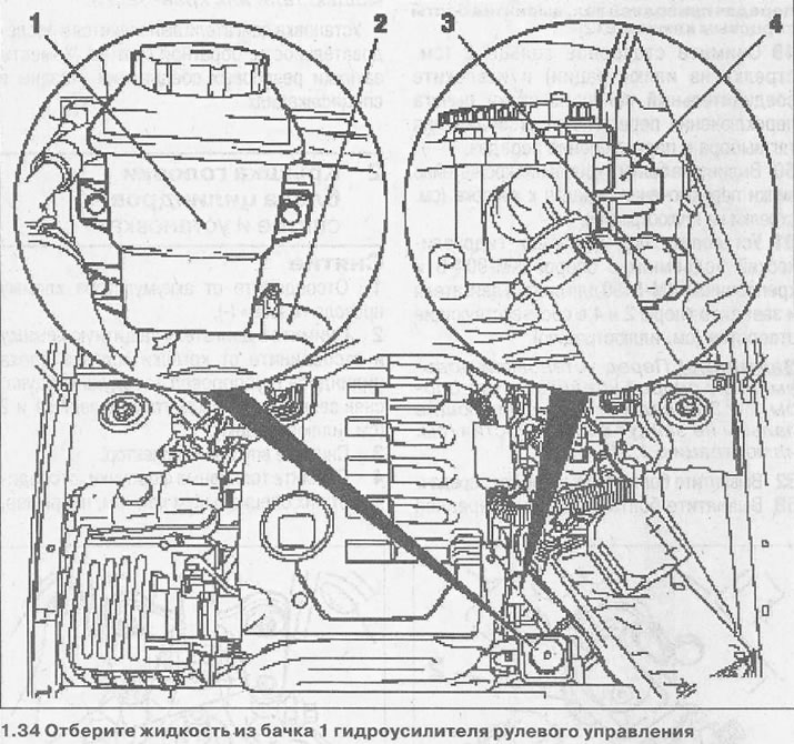
Attention! Do not allow liquid to come into contact with the generator.
35. Disconnect the pressure pipe 2 from the power steering pump, collecting the liquid flowing from them (see illustration 1.34).
36. Disconnect bracket 4 from the power steering pump, on which the pressure pipe is attached (see illustration 1.34).
37. Disconnect pipeline 3 from the hydraulic booster pump and collect the flowing liquid (see illustration 1.34).
38. Unscrew bolts of fastening and remove forward wheels.
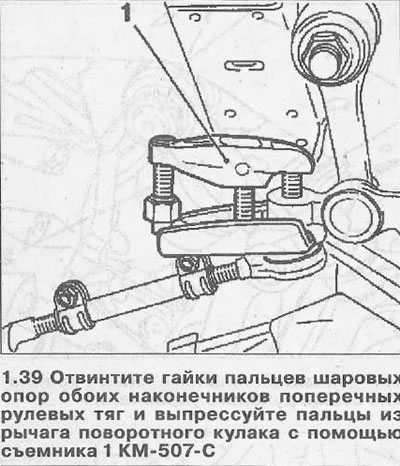
39. Unscrew the nuts of the pins of the ball bearings of both ends of the transverse steering rods and press the pins out of the steering knuckle lever using the puller 1 KM-507-C (see illustration).
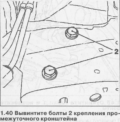
40. Unscrew the bolts 2 fastening the intermediate bracket (see illustration).
41. Remove the cap from the nut 1 of the steering bipod mounting and unscrew the nut, marking the mounting position of the bipod (see illustration).
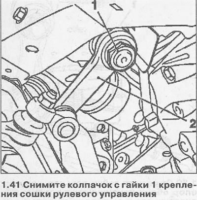
42. Press out the finger of the lever 2 bipod using the KM-146-01 puller (see illustration 1.41).
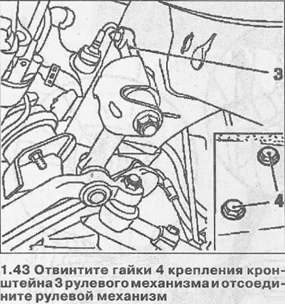
43. Unscrew the nuts 4 fastening the bracket 3 of the steering gear and disconnect the steering gear (see illustration).
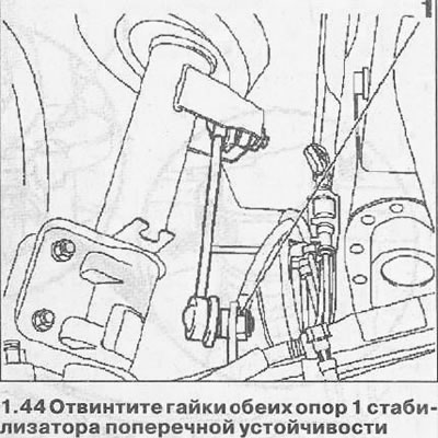
44. Unscrew the nuts of both supports 1 of the anti-roll bar (see illustration).
45. Unscrew the nuts 1 and remove the bolts (see illustration).
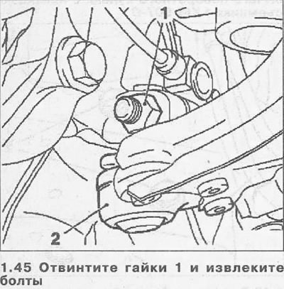
46. Press out the fingers of the ball bearings 2 fastenings of the lower guide levers to the steering knuckles (see illustration 1.45).
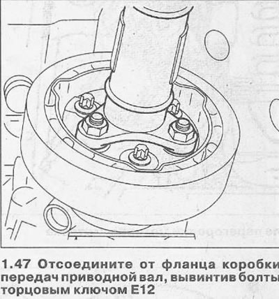
47. Disconnect the drive shaft from the gearbox flange by unscrewing the bolts with an E12 socket wrench (see illustration). After unscrewing the mounting bolts, press the axle shaft with a pry bar and secure it with wire on the body.
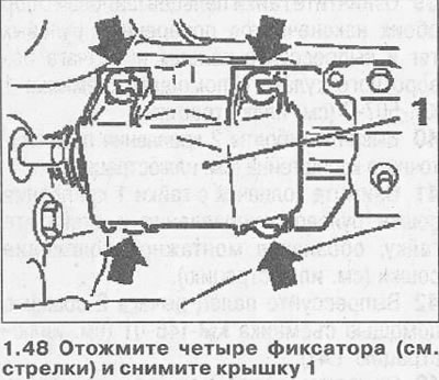
48. Press out the four latches (see arrows in illustration) and remove cover 1, which closes the connection of the lever with the gear change mechanism. The removal cover must be pushed forward.
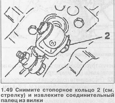
49. Remove retaining ring 2 (see arrow in illustration) and remove the connecting pin from the shift lever fork to disconnect the select and shift rods.
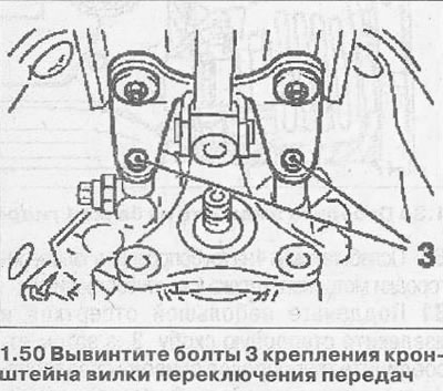
50. Unscrew the bolts 3 fastening the bracket of the shift fork to the box (see arrows in illustration).
51. Install a hydraulic lift under the engine with a KM-904-B support and KM-6190 mounts to remove the engine and insert stops 2 and 4 into the corresponding holes (see illustration).
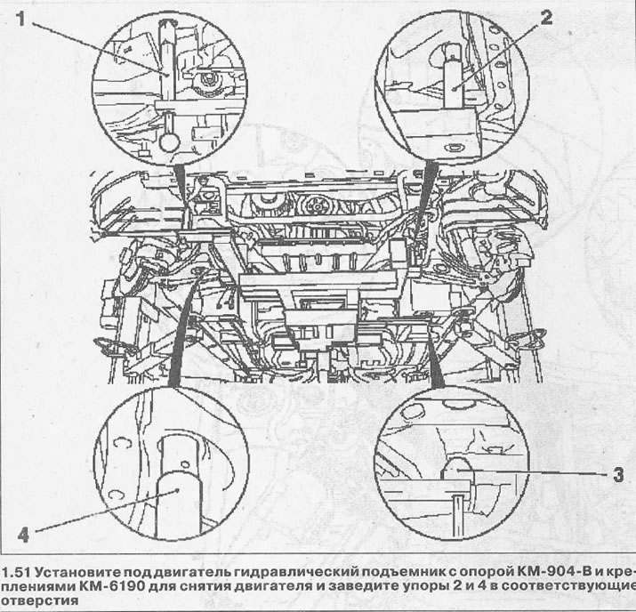
Attention! Before installing the lift with the support, make sure that the supports 1 and 3 are out and the centering pins will not go into their holes (see illustration 1.51).
52. Unscrew bolts of a support of a transmission.
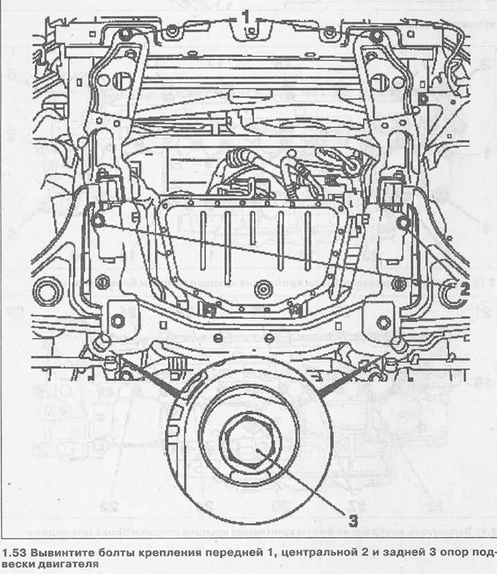
53. Unscrew the bolts of the front 1, center 2 and rear 3 engine mounts (see illustration).
54. Lower the lift with the power block lying on the support and take the block out from under the front of the car.
Attention! Removing the engine in this way requires precautions and the use of a special mounting support. In the absence of a mounting support, removal of the engine from the engine compartment by loading onto a garage lift is not allowed. This can cause severe engine damage. In this case, the engine should be removed using a hoist or crane beam.
The engine is installed in the reverse order of removal. The tightening torques for threaded connections are specified in specifications.
Visitor comments