
Removing camshafts
1. Remove the alternator drive belt.
2. Remove the cylinder head cover (see relevant chapter).
3. Remove the vacuum pump (see relevant chapter).
4. Disconnect the cooling hose from the cylinder head.
5. Unscrew the plug from the cylinder block and lock the crankshaft at TDC of the piston of cylinder No. 1 with thrust pin 1, turning the crankshaft by the bolt of the vibration damper to the belt pulley (see illustration).
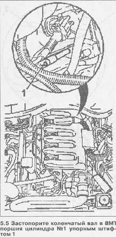
At TDC of the piston of cylinder No. 1, the cams of the piston valve actuator must face each other (see arrows in illustration 5.6).
6. Remove the chain damper 1 and plug 2 from the casing of the timing gear (see illustration).
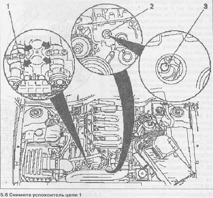
7. Loosen bolt 3 of the hydraulic chain tensioner (see illustration 5.6).
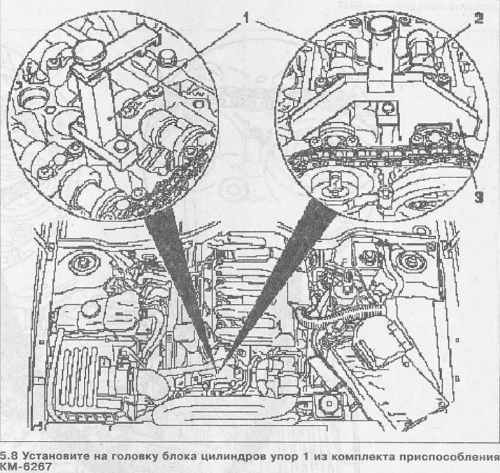
8. Install stop 1 from the KM-6267 tool kit on the cylinder head, and then fix the intake camshaft 2 with tool 3 (see illustration).
9. Slowly turn the exhaust camshaft by the drive sprocket bolt in the direction as shown by the arrow in the illustration to loosen the chain tension by compressing the tensioner.
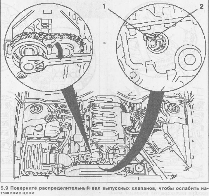
10. After loosening the chain, insert the thrust pin 1 KM-823 into hole 2 on the tensioner and fix it (see illustration 5.9).
Attention! If the camshaft sprockets are removed without locking the chain tensioner, the tensioner piston will slip out. Its subsequent installation will require considerable effort and time.
11. Unscrew the bolts 1 and 2 fastening the camshaft sprockets, holding the shafts from turning by the hexagons (see illustration).
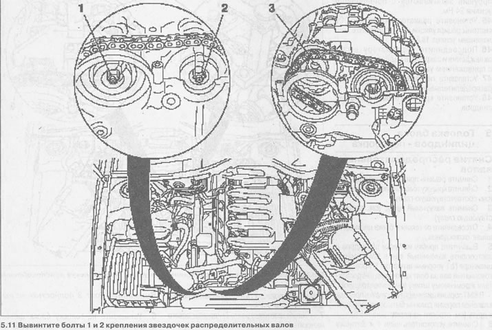
12. Remove chain 3 by lifting it up from the exhaust camshaft drive sprocket, and then remove the sprocket from the shaft (see illustration 5.11).
13. Remove the sprocket from the intake camshaft.
14. Remove thrust devices KM-6267 from the cylinder head.
Attention! To avoid damaging the valves when installing the camshafts, the cylinder pistons must not be at TDC.
15. Remove the thrust pin 1 KM-813 and turn the crankshaft 90°in the direction of engine rotation by the vibration damper fastening bolt on the belt pulley (see arrow in illustration). While doing this, keep the timing chain tensioned.
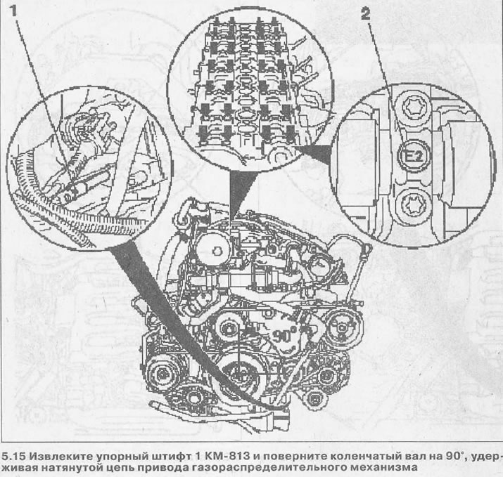
16. Unscrew the bolts securing the camshaft bearing caps, after loosening them by 1/2 turn and marking the covers (see arrows in illustration 5.15).
17. Remove the camshaft bearing caps and lay them so that they can be installed in their original places during assembly. The lids are also marked 2 (see illustration 5.15).
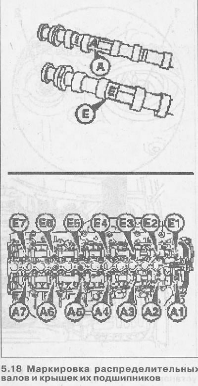
18. Remove camshafts. When installing the shafts, follow the marks stamped on them. The letter E is printed on the intake camshaft, and A is on the exhaust valve shaft (see illustration). The corresponding marking is also on the camshaft bearing caps. The intake camshaft covers are marked E1-E7, and the exhaust camshaft A-A7 (see illustration).
19. Lubricate the camshaft bearing journals with engine oil and lay them in their mounting locations.
Lubricate the working surfaces of the camshaft bearing caps and install the camshaft bearing caps, observing the designations made before removal or their markings.
Attention! To ensure the desired position of the camshafts, tighten the cap bolts as indicated below.
20. Screw in and tighten the cap bolts by hand, and then tighten them ½ turn, working from the center to the ends.
21. Make a second pass and tighten the bolts to 10 Nm.
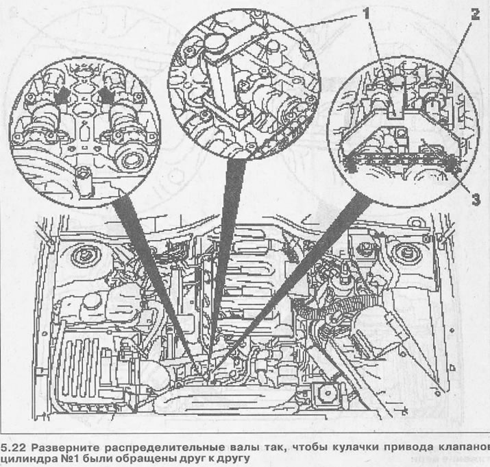
22. Turn the camshafts by the hexagons so that the cams of the valve actuator of cylinder No. 1 are facing each other (see arrows in illustration).
23. Install stop 1 from the KM-6267 tool kit on the cylinder head, and then fix the intake camshaft 2 with tool 3 (see illustration 5.22).
24. Lay chain 3 on the intake camshaft sprocket and install the sprocket on the shaft (see illustration).
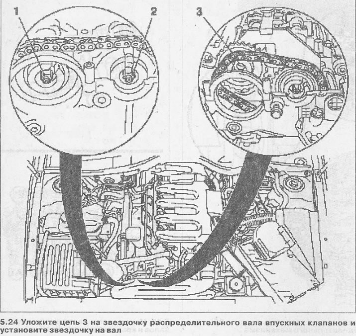
25. Screw in a new bolt 2 fastening the sprocket to the shaft, tighten it, and then tighten it ½ turn (see illustration).
26. Bring the camshaft sprocket down, put a chain on it and fix the sprocket with the chain on the exhaust camshaft.
27. Screw in a new bolt 1 fastening the sprocket on the exhaust camshaft, but do not tighten it (see illustration 5.24).
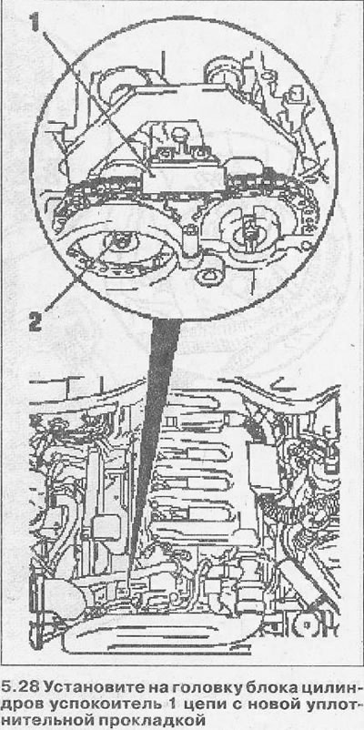
28. Install chain damper 1 with a new gasket on the cylinder head and bolt with a force of 9.9 Nm (see illustration).
29. Tighten the bolt 2 fastening the sprocket on the exhaust valve shaft with a force of 15 Nm, holding the shaft from turning by the hexagon (see illustration 5.28).
30. Slowly turn the exhaust camshaft by the drive sprocket mounting bolt in the direction as shown by the arrow in the illustration to loosen the chain tension by compressing the tensioner.
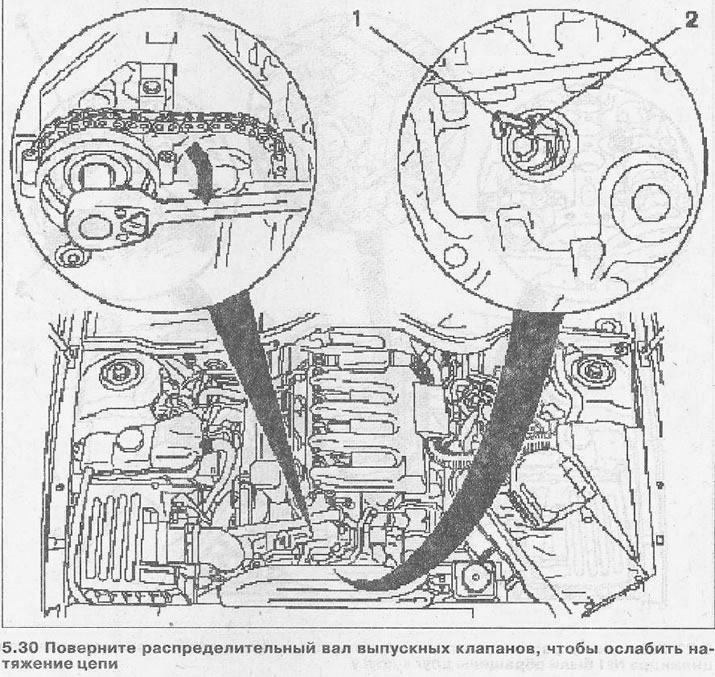
31. After loosening the chain, insert the thrust pin 1 KM-823 into hole 2 on the tensioner and fix it (see illustration 5.30).
32. Loosen the sprocket mounting bolt on the exhaust camshaft by ½ turn.
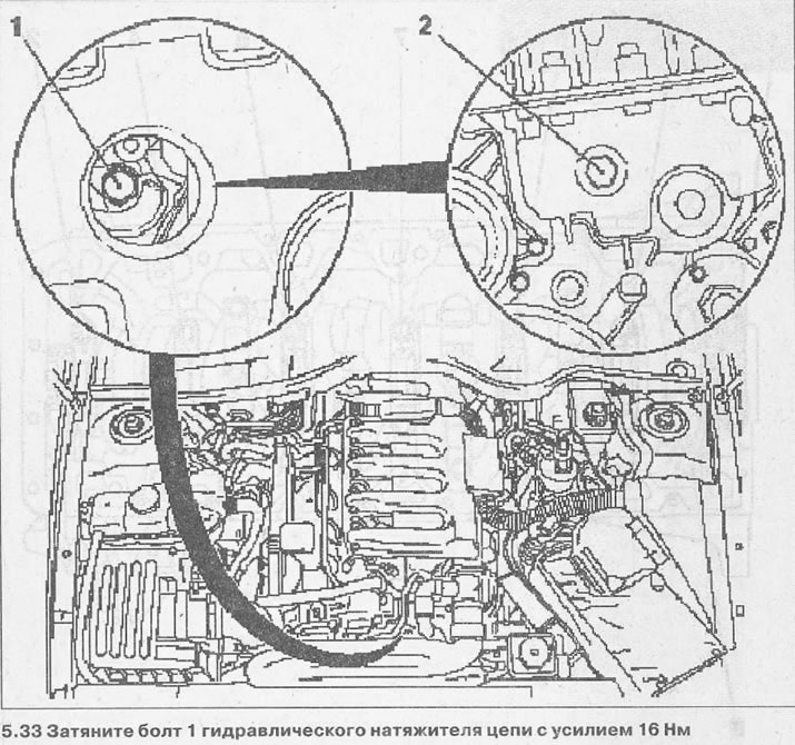
33. Tighten the bolt 1 of the hydraulic chain tensioner with a force of 16 Nm (see illustration).
34. Put a sealing gasket on plug 2 and screw it into the casing of the gas distribution mechanism drive with a force of 30 Nm (see illustration 5.33).
35. Stop the crankshaft at TDC of the piston of cylinder No. 1 with the stop pin KM-813, turning the crankshaft by the bolt of the vibration damper to the belt pulley (see illustration 5.6).
36. Tighten the bolt 3 fastening the intake camshaft sprocket with a force of 20 Nm, and then tighten it by 35°, while keeping the camshaft from turning (see illustration).
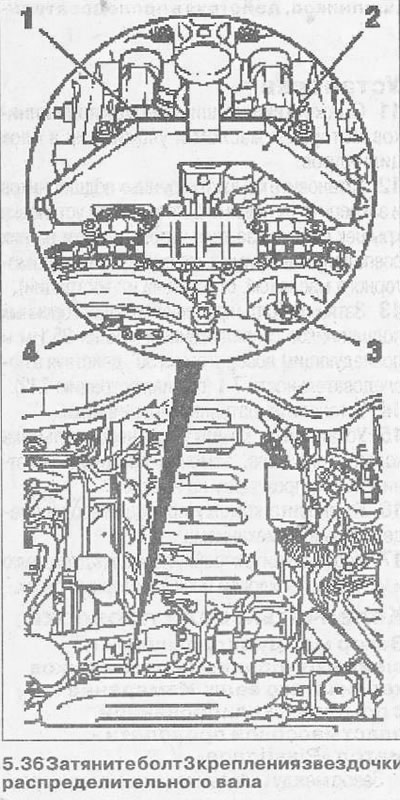
37. Install stop 2 from the KM-6267 tool kit on the camshaft 1 of the exhaust valves and achieve a tight fit of the support surfaces of the tool on the cylinder head (see illustration 5.36).
38. Tighten the bolt 4 fastening the sprocket on the exhaust camshaft with a force of 20 Nm, followed by turning the bolt 35° (see illustration 5.36).
39. Remove the thrust fixture from the exhaust camshaft and remove the KM-813 pin from the hole on the flywheel drive disk.
40. Turn the crankshaft for the vibration damper mounting bolt on the accessory drive belt pulley two turns (720°) in the direction of engine rotation and fix the crankshaft with the thrust pin KM-813, inserting it into the hole on the flywheel / drive disk.
41. Install thrust devices KM-6267 on the intake and exhaust camshafts. The tools must fit snugly against the sealing surfaces of the cylinder head. If this is not the case, then the installation of the camshafts should be repeated.
Installation of parts dismantled from the cylinder head is performed in the reverse order of removal.
Visitor comments