
Tightening torques for threaded connections, Nm
- Bolts of fastening of a starter to transmission — 47
- Drive disc to crankshaft - 120
- Exhaust manifold to cylinder head - 23
- Oil filter cap - 25
- Cover of a drive of the gas-distributing mechanism to the block of cylinders — 22
- Vibration damper to the crankshaft - 40 + turn by 60°and 60°
- Fuel pressure regulator to high pressure fuel pump - 9
- Intake manifold to cylinder head, bolts M6 - 10
- Intake manifold to cylinder head, bolts M7 - 15
- Accelerator pedal to bulkhead - 20
- Fuel line to injection pump - 30
- Fuel line to the injector rail - 30
- High pressure fuel pump to cylinder block - 25
- Nut of a finger of a spherical support of the directing lever to a rotary fist — 100
- Timing chain damper - 9.9
- Support legs to the anti-roll bar - 65
- Generator to the casing of the gas distribution mechanism drive - 47
- Oil pan, bolts M10 - 40
- Transmission to the cylinder block, bolts M12 - 60
- Transmission to the bottom - 45
- Glow plugs - 18
- Arm of the compressor of the conditioner to a casing of a drive of the gas-distributing mechanism — 24
- Boost air pressure reducing valve - 9.9
- Bracket of a forward support of the engine to the block of cylinders — 24
- Bracket of the intermediate support to the bottom - 55 + turn by 75°and 15°
- The rear cover of the timing mechanism to the cylinder block, M6 bolts - 9.9
- The rear cover of the timing mechanism to the cylinder block, bolts M8 - 24
- Pressure fuel line to high pressure fuel pump - 20
- High pressure fuel pump to cylinder block - 24
- Pressure oil pipeline to the hydraulic booster pump - 37.5
- Crankshaft position sensor to cylinder block - 9.9
- Camshaft position sensor to cylinder head cover - 3.5
- Tensioner ribbed belt to the casing of the gas distribution mechanism - 14.8
- Asterisk to the injection pump shaft - 65
- Asterisk to the oil pump shaft - 24
- Chain tensioner to cylinder block - 16
- Coolant drain plug from cylinder block - 25
- Water pump to cylinder block - 15
- Bolts of caps of main bearings to the block of cylinders — 25 + dorotat on 50°
- Bipod steering to the steering gear - 160
- EGR solenoid valve - 9.9
- Front engine mount to subframe - 55
- Left engine mount to bracket - 47
- Right engine mount to bracket - 47
- Bolts of covers of bearings of a camshaft to the block of cylinders — 10
- Asterisk to the camshaft - 20 + 35°turn
- Drain plug in the oil pan - 10
- Oil pressure sensor to oil filter housing - 14
- Oil filter to cylinder block - 22
- Oil filter cap - 25
- Oil dipstick guide - 9.9
- Oil pump to cylinder block - 23
- Oil return line to turbocharger - 9.9
- Oil supply line to the turbocharger - 25
- Oil supply line to cylinder block - 25
- Oil pan to the cylinder block, bolts Mb - 10
- Oil pan to the cylinder block, M8 bolts - 21.5
- Connecting rod bearing cap bolts - 20 + 60°turn
- Wheel bolts - 110
- Flywheel to crankshaft - 105
- Coolant temperature sensor - 13
- Boost air pressure sensor to intake manifold - 9.9
- Engine oil temperature sensor - 18
- High pressure fuel pump to flange - 28
- The tip of the transverse tie rod to the steering knuckle - 60
- Turbocharger bracket to turbocharger - 24
- Turbocharger bracket to cylinder block - 24
- Thermostat housing - 9.9
- Turbocharger to exhaust manifold - 50
- Guide roller - 24
- Vacuum pump to cylinder block - 22
- Chain tensioner to timing case -! - thirty
- Viscous fan clutch radiator - 10
- Fan with viscous coupling to the water pump - 40
- Front engine mount - 65 + turn by 30°and 15°
- Central engine support - 150 + turn 30°and 15°
- Rear engine mount - 130 + turn 30°and 15°
- Cylinder head to timing gear housing - 15 (M7 bolts)
Head to cylinder block
- 1 Tighten the bolts to 80 Nm.
- 2 Loosen the bolts by 180°.
- 3 Tighten the bolts to 50 Nm.
- 4 Tighten the screws by 90°.
- 5 Tighten the bolts by 90°.
Cylinder head cover - 10
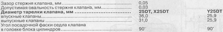
Cylinder head and valves (see illustration 0.0)
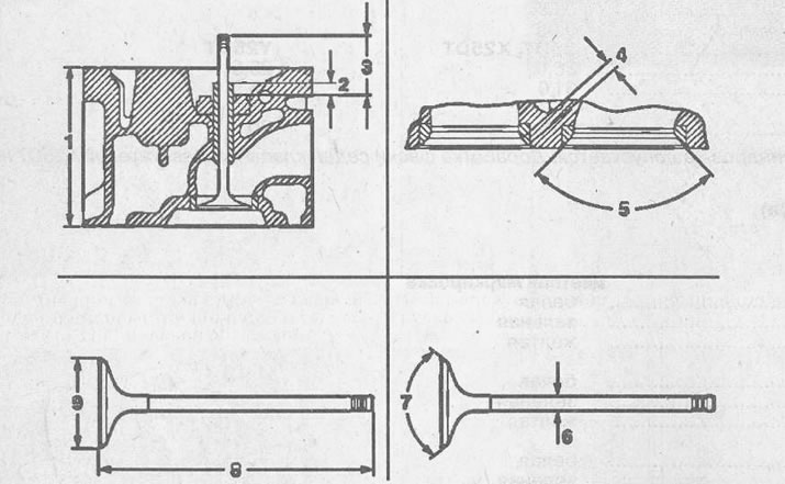
0.0 Cylinder head and valves
1 head height
2 valve guide lug
3 valve stem protrusion
4 valve seat width in cylinder head
5 seat angle of the valve seat in the cylinder head
6 valve stem diameter
7 valve seat bevel angle
8 valve stem length
9 valve disc diameter
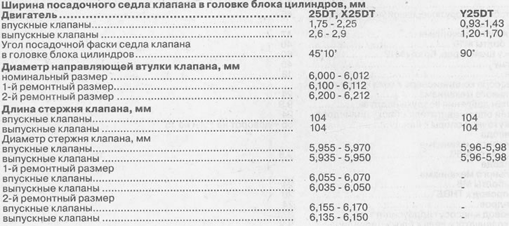
Attention! Grinding of the cylinder head is not permitted. Valve seat chamfering on Y25DT engines is not permitted.
Crankshaft (see illustration 0.0a)
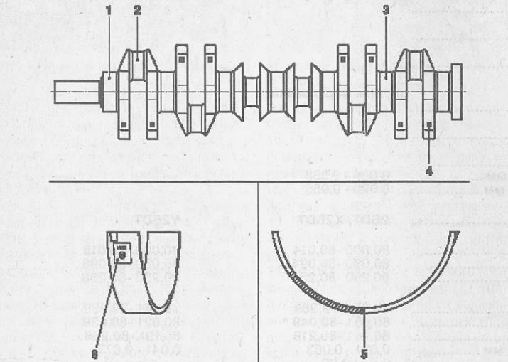
0.0a Crankshaft
1 main bearing journals
2 connecting rod journals
3 neck of the middle main bearing
4 color marking
5 color coded inserts
6 insert designations
Diameter of necks of a cranked shaft, mm
main bearings
nominal size - color marking
- 59.971 -59.976 - white
- 59.977 - 59.983 - green
- 59.984-59.990 - yellow
1st repair size (0,25)
- 59.721 - 59.726 - white
- 59.727 - 59.733 - green
- 59.734 - 59.740 - yellow
2nd repair size (0,50)
- 59.471 - 59.476 - white
- 59.477 - 59.483 - green
- 59.484 - 59.490 - yellow
connecting rod bearings
nominal size - color marking
- 44,991-44,975
1st repair size (0,25)
- 44,741 - 44,725
2nd repair size (0,50)
- 44,491 -44,475
middle neck
nominal size - color marking
- 25,020-25,053
1st repair size (0,25)
- 25,220-25,253
2nd repair size (0,50)
- 25,420-25,453
Nominal clearance of main bearings, mm - 0.020 - 0.058
Rated clearance of connecting rod bearings, mm - 0.020 - 0.055
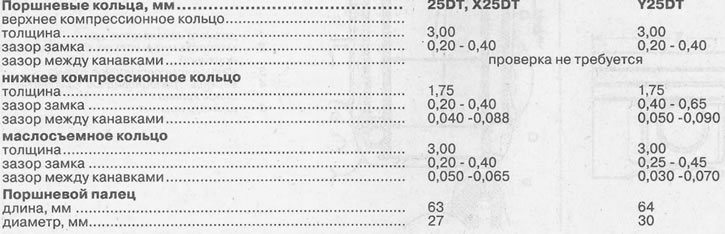
Cylinder block (see illustration 0.0b)
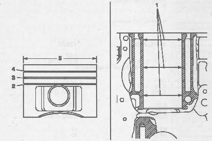
0.0b Cylinder block
1 cylinder bore diameter
2 oil scraper ring with expansion spring
3 lower compression ring
4 top trapezoidal compression ring
5 piston diameter
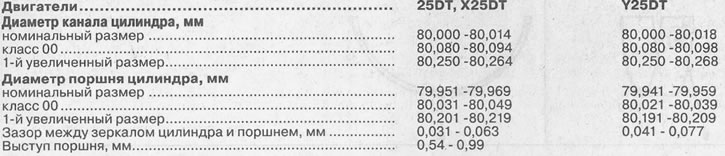
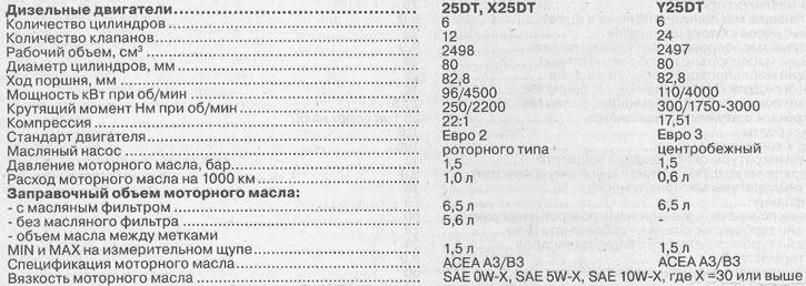
Engines 25DT, X25DT
Piston protrusion - 0.54 - 0.99 mm
Head Gasket Thickness - Number of Notches
- 1.87 mm - 3
Y25DT engine
Head Gasket Thickness - Number of Notches
- 1.45 mm - 1
- 1.55 mm - 2
- 1.65 mm - 3
Visitor comments